Aperture synthesis. Laser ranging, Doppler imaging and aperture synthesis Processing in synthetic aperture antennas
17. RADAR STATIONS WITH SYNTHESIS APERTURE ANTENNA (SAR)
Radars with a long fuselage antenna make it possible to obtain detailed radar images only at relatively short ranges. When moving the reconnaissance strip tens of kilometers from the aircraft, it is necessary to use antennas tens and hundreds of meters long, which cannot be placed on the aircraft.
To overcome this difficulty, the method of synthesizing the antenna aperture is used, which consists in storing signals reflected from targets in a section of the flight path, the length of which is equal to the required antenna length. Subsequent processing of the recorded signals in on-board or ground-based equipment makes it possible to obtain a radar image with high detail.
IN Currently, optical processing systems are most widespread. They are based on the holographic method, in which radar signals (radio holograms) recorded on film are used to form a radar image.
IN The SAR principle of holography is used both in recording reflected radio waves and in OOS optical devices.
The reference wave, passing through the hologram, creates an image of the object exactly in the place where it was at the time the hologram was recorded. Image
(dots) will not be pointy, but somewhat blurry. The spot size δ x, which determines the detail of the created image, can be found from the following expression:
δ x = λ R/X;
where λ is the irradiating wavelength; R - Distance from the hologram to the object; X is the linear size of the hologram.
Let us formulate the main features of the holographic process:
- it is necessary to have coherent reference and signal waves;
- in the process of holography, the amplitude-phase distribution of the signal wave field is recoded into the amplitude distribution of the signal and this signal is recorded in the form of a hologram (interference pattern);
- To restore the image, it is necessary to irradiate the hologram with a reference wave.
Glograms have a number of interesting properties. One of them is the possibility of changing the image scale. If you simultaneously change the linear size of the hologram and the wavelength of the light beam restoring the image by the same number of times, then by the corresponding number of times
The scale of the created image will also change. If the changes in the wavelength and scale of the hologram are disproportionate, then the image will also be formed, but large-scale distortions will appear in it. In many practical applications these distortions do not play a significant role.
This property allows you to record holograms at one wavelength, for example in the radio range, and reconstruct the wavefront and observe the image at another wavelength, in the optical range.
Consider a side-scan radar system installed on board an aircraft, as shown in Fig. 17.1. Let us assume that a sequence of pulsed radar signals is directed towards the terrain from a radar system on an aircraft and that the reflected signals, depending on the reflectivity of the terrain, are received from a site close to the aircraft's heading. Let us call the coordinate of the radar image transverse to the flight direction “range”, and the coordinate coinciding with the flight path “azimuth”. It is also convenient to call the coordinate connecting the radar path on the aircraft to any target in question the “slant range.” If a conventional radar system is used, then the azimuth resolution will be of the order of λ r1 /D, where λ is the wavelength of the radar signals, r1 is the slant range, D is the size of the antenna aperture along the flight path. However, the wavelength of the radar signal is several orders of magnitude larger than the optical wave and, therefore, in order to obtain an angular resolution comparable to that of a photo reconnaissance system, a very large antenna aperture D is required. The required antenna length can be tens or even hundreds of meters. Obviously, this is difficult to implement on an airplane.
However, this difficulty can be overcome by using the synthetic aperture method. The basic principle of aperture synthesis is that different array elements do not necessarily have to exist simultaneously in space. Let's assume that the aircraft has a small side-scan antenna and that a relatively wide radar beam scans the area due to the movement of the aircraft. The aircraft positions at which radar pulses are emitted can be considered as elements of a linear antenna array. The received signal at each of these positions is then recorded coherently as a function of time, since a reference signal is supplied to the radar receiver, allowing both amplitude and phase information to be recorded simultaneously. The various recorded complex waves are then processed accordingly to synthesize the actual aperture.
To study in more detail how this method of antenna synthesis is implemented, we first consider the problem with a point target and then extend the results obtained using the superposition method to a more complex case. Let's assume that the point target is at point x1.
The radar pulse is generated by periodic rectangular modulation of a sinusoidal signal with an angular frequency equal to ω.
Azimuth Field of View
where A1 is the corresponding complex constant. The complex quantity A1 includes factors such as radiated power, target reflectivity, phase shift and propagation law (inversely proportional to the fourth power of power). Using the paraxial approximation, the range r can be written as follows:
where k = 2π /λ. Expression (17.3) depends on t and x, and the spatial and temporal variables are related to each other by the relation
where v is the speed of the aircraft. If we now assume that the terrain at a distance r1 consists of a set of n point targets, then, using the superposition method, we write the total reflected signal in the form
S(t) = ∑ An (xn ,r1 )exp(i[ω t-2kr1 -k(vt-xn )2 /r1 ]). (17.5) n=1
If the reflected radar signal, described by (17.5), is demodulated using a synchronous detector, then the demodulated signal can be written as follows:
S(t) = ∑ An (xn ,r1 ) cos[ω c t-2kr1 -k(vt-xn )2 /r1 +ϕ n ], (17.6) n=1
where ω c is an arbitrary carrier frequency, and ϕ n is an arbitrary phase angle. To store the reflected radar signal, use
cathode ray tube. The demodulated signal supplied to it modulates the intensity of the electron beam, which unfolds in the vertical direction synchronously with the reflected radar pulses. If the signal image from the tube screen is projected onto photographic film, which moves horizontally at a constant speed, then a sequence of range traces will be recorded, which will form a two-dimensional image (Fig. 17.2). The vertical lines describe the range sweep, and the azimuth positions are plotted horizontally. Thus, the recorded image is a set of samples of the signal S(t). This sampling is carried out in such a way that by the time the signals are recorded on film, it turns out to be substantially indistinguishable from the original signal. With such recording, it is obvious that time variables are converted into spatial variables in distance values along the recording line. When properly exposed, the transparency of the recording film represents the change in azimuth of the reflected radar signal. Thus, if we consider only the data recorded in the direction y = y1, the amplitude transmittance can be represented as
)2 +ϕ |
||||||||||||||
∑A(x |
) cos[ω x-2kr |
|||||||||||||
r 1 v f |
||||||||||||||
Range (y)

Trace of modulated Azimuth (x) by electron beam brightness
where K1 and K2 are the displacement and proportionality coefficient, x=vf t is the film coordinate; vf is the speed of film movement; ω x =ω c /vf . Since the cosine can be represented as the sum of two complex conjugate exponentials, the sum in (7.75) can be written as two sums T1 and T2:
) exp(i[ω x-2kr |
)2 (x-x |
/v)2 +ϕ |
|||||||||||||||||||||||
)=---- ∑ A |
|||||||||||||||||||||||||
)2 (x-x |
/v)2 +ϕ |
||||||||||||||||||||||||
)=---- ∑ A |
) exp(-i[ω x-2kr |
||||||||||||||||||||||||
For simplicity, we will limit ourselves to a task for one goal. Then for n = j equation (17.8) takes the form
) = Cexp(iω x)[-i--- (----)2 (x - x |
/v)2 ], |
||||||
where C is the corresponding complex constant. The first exponent describes the linear phase function, i.e. simply the slope of the emitted wave. The angle of inclination to the film plane is determined by the expression
Thus, excluding the linear phase function, (7.76) is a superposition of N positive cylindrical lenses centered at the points given by
x = vj xn /v, |
n = 1, 2, ..., N. |
Similarly, (17.9) contains a linear phase factor - 0 and describes the superposition of N negative cylindrical lenses with centers defined by (17.14) and focal lengths described by (17.13).
To restore the image, the transparency corresponding to (17.7) is illuminated with a monochromatic plane wave, as shown in Fig. 17.3. It can then be shown, using Fresnel-Kirchhoff theory or Huygens' principle, that the real images produced by T1(x,y1) and the virtual images produced by T2(x,y1) will be reconstructed at the front and rear focal planes of the film. The relative positions of the images of the point scatterers are distributed along the line of foci, since the multiple centers of the lens-like structure of the film are determined by the position of the point scatterers. However, the reconstructed image will be blurred in the y direction; that is why this film is essentially a realization of a one-dimensional function along y = y1 and, therefore, there is no focusing effect in this direction.
Since our goal is to reconstruct the image not only in the azimuthal direction but also in the range direction, it is necessary to display the y-coordinate directly on the focal plane of the azimuthal image. To accomplish this, it is necessary to recall that it is directly proportional to the range r1. In turn, the focal length is directly proportional to the y coordinate being considered. Thus, to create a terrain map, we must map the y-coordinate of the transmitted signal onto a plane whose position is determined by the focal lengths of the azimuthal direction. This is easily accomplished by installing a positive conical lens directly behind the recording film, as shown in Fig. 17.4. Obviously, if the transmittance of a conical lens is equal to
x2/2f), |
||||||

f is a linear function of r1, as shown in (17.13), then we can completely remove the entire named plane of all imaginary diffraction to infinity, while leaving the transmittance in the y direction unchanged. Thus, if a cylindrical lens is placed at the focal length of a film transparency, the virtual image in the y direction will be at infinity. Let the azimuthal image and the image in the range direction (i.e. in the x and y directions) be the same, but at a point at infinity. They can be transferred back to a finite distance using a spherical lens. With this operation, the actual image of the terrain coordinates in azimuth and range will be focused on the output plane of the system. However, in practice, the desired image is recorded through a slit in the output plane.
The developed secondary film can be examined and deciphered.
APERTURE SYNTHESIS, a method of obtaining high angular resolution by synthesizing the results of measurements performed by a radio interferometer, consisting of two small apertures moving within a large aperture, and a correlation (multiplying) receiver. The measurement result using the aperture synthesis method is similar to measurements with a large aperture antenna. With aperture synthesis, a large number of measurements are performed at different positions of the elements and the results are summarized with certain weights and phases.
The aperture synthesis method was proposed in 1952 by M. Ryle, who used it to study the radio structure of galaxies. In 1974, Ryle and E. Hewish were awarded the Nobel Prize “for their pioneering research in radioastrophysics.” Aperture synthesis is most widespread in radio astronomy and radar. In radio astronomy, aperture synthesis is used in connection with the problems of studying the angular distribution of the radiation intensity of a radio source with a fine structure from arcminutes to fractions of seconds. For such studies, antennas with a ratio d/λ (d is the linear size of the aperture, λ is the wavelength) of the order of 10 3 -10 6 are needed, therefore for the centimeter range of radio waves d should be on the order of hundreds of meters or more. Naturally, it is impossible to create conventional antennas with such an aperture, so the aperture is “synthesized” by taking measurements at individual points located inside this synthesized aperture and performing appropriate measurement processing. The result is high angular resolution.
When using the aperture synthesis method, a large antenna is divided into N elements. The incident waves, reflected from each element, arrive at the focus of the antenna in phase. Therefore, the high-frequency voltage V(t) at the focus can be written as the sum of the components ΔV i (t) from individual elements:
The power P at the receiver output of a large antenna is proportional to the average value of the square of the voltage:
From formula (2) it is clear that the measurement result contains terms that depend on the signals received only from pairs of elements. Each term can be measured using two small antennas of size equal to the aperture element, located in positions i and k, and a correlation (multiplying) receiver. If the observed area of the sky does not contain variable sources, then such an interferometer can be used to sequentially measure the terms of the series (2).
A segment of the east-west line on the Earth's surface, visible from a distant source, rotates 180° in 12 hours. If all elements of the antenna array on this segment follow the source, then in 12 hours it is possible to synthesize a circular aperture in a plane perpendicular to the Earth’s rotation axis, with a diameter equal to the length of the segment. The width of the synthesized diagram in any direction is inversely proportional to the projection of the aperture in this direction. The deterioration of resolution in directions close to the equatorial plane is eliminated by using a T-shaped antenna array with segments oriented in the east-west and north-south directions (Fig.).

Modern aperture synthesis systems consist of a large number of fully rotating antennas and simultaneously operating independent correlation interferometers, which significantly reduces observation time. Rotating together with the Earth, each interferometer measures a large number of terms of the series (2). For multi-element interferometers, the aperture synthesis method makes it possible to synthesize a beam with a width that can be obtained with an aperture having dimensions comparable to the dimensions of the antenna array.
To more fully extract information from measurement results, a priori information about the brightness of the sky is used. Such a priori information allows the use of widely spaced antenna systems, as well as the construction of sky maps using only amplitude measurements when phase information is unreliable or absent.
The first work using small movable antennas for aperture synthesis was carried out in Cambridge (UK) in 1954. In Sydney (Australia) in 1956, the Earth's rotation was first used to synthesize a two-dimensional lattice using a linear one. The most famous aperture synthesis system is the VLA (Very Large Array) antenna array in New Mexico (USA), completed in 1981. It consists of 27 fully rotating paraboloids with a diameter of 25 m each, which can move along three 21-kilometer rail tracks laid in the shape of the letter Y. The angular resolution of this system at a wavelength of 1.3 cm is 0.05".
The aperture synthesis method is also used in interferometers formed by antennas separated by hundreds and thousands of kilometers (radio interferometers with ultra-long bases). This makes it possible to synthesize apertures comparable to the size of the Earth and obtain an angular resolution of the order of 0.001", far superior to what has been achieved in optical astronomy. In the future, there is the creation of Earth-space apertures, some of the elements of which will be placed on spacecraft (Radioastron project, Russia) .
Lit.: Kraus J.D. Radio astronomy. 2nd ed. Powell, 1986; Christiansen U., Hogbom I. Radio telescopes. M., 1988.
Technical task
Develop RTS :
RTS type……………....aircraft;
Purpose. ……………Side-looking synthetic aperture radar;
Tactical and technical characteristics of the developed RTS:
1 Analysis of technical specifications
In aircraft radars, there are strict restrictions on the dimensions of the antennas, which prevents the achievement of azimuth resolution.
To overcome this obstacle, one of two methods implemented in side-looking radar is used. In the first case, the antenna is located along the fuselage, which makes it possible to significantly increase its size and thereby improve its resolution. The second method uses an artificial increase in the size of the antenna due to the so-called aperture synthesis.
According to the technical specifications, it is required to develop an aircraft side-looking radar with a synthetic aperture. In such radars, a large antenna is installed motionlessly along the fuselage of the aircraft. The beam of the antenna system is directed perpendicular to the axis of the aircraft. Usually two antennas are installed, the beams of which are directed to the right and left of the flight direction. Viewing a given area of the earth's surface occurs due to the movement of the aircraft itself during flight (Figure 1).
 |
Figure 1 – The principle of viewing space in a direction perpendicular to the axis of the aircraft.
The operating principle of synthetic aperture radar (SAR) is based on creating equivalent apertures with an increased effective length, which is achieved using special signal processing methods, rather than increasing the physical dimensions of the aperture of a real antenna. SAR uses only one antenna-emitting element (a real antenna), which sequentially occupies a position along the flight path. At each of these positions, signals are emitted and received (Figure 2).
The signals reflected from the targets, both the amplitude and phase of the received signals, are stored in a memory device,

Figure 2 – The principle of the formation of an artificial (synthesized) opening.
After the resulting displacement of the radiating element by an amount, the signals in the memory device become very similar to the signals that were received by the elements of the real linear array. If the signals in the memory are processed using the same algorithm as when forming a real linear array, we will obtain the effect of receiving signals at a large antenna (the “aperture synthesis” method).
In addition, in SAR, signals in the memory can be selected by range and, if necessary, signals of different ranges can be processed in different ways (focusing).
When turning, the aircraft begins to roll, resulting in an error in altitude measurement. To eliminate the error, it is necessary to fix the antenna on a balancing device, as a result of which the main lobe of the antenna's radiation pattern is directed perpendicular to the earth's surface.
Typically, side-view RTS uses a pulse-modulated signal.
The antenna has a cosecant radiation pattern.
In order not to worsen the aerodynamic properties of the aircraft, the antenna is placed under a special fairing that does not interfere with the passage of the radio signal. In the calculations, it is necessary to take into account that the aircraft is located over different types of earth's surface, which have different reflective properties.
2 Features of the construction of some synthetic aperture radar units.
Antenna
The horizontal size of the RSL antenna aperture determines the linear azimuth resolution practically achievable in a synthetic aperture radar. When processing signals, it is assumed that the gain of a real antenna during the flight of an aircraft remains constant. Therefore, it is necessary to have the antenna pattern stabilized so that the residual beam oscillations are significantly smaller than the pattern width. In most cases, the antenna is installed laterally.
Transceiver
In a synthetic aperture radar, it must provide high signal coherence. Consequently, more stringent requirements are imposed on the stability of the generator frequency and element parameters. The output of a coherent radar is the voltage at the output of a synchronous detector. The output signal is a bipolar video signal in which the reference offset level corresponds to the signal's zero offset.
Signal recording and memorization.
A characteristic feature of SAR is the need to memorize the received signals, since the signals necessary for the formation of a synthesized pattern are received at the input not simultaneously, but over a certain time interval. Processing of stored signals allows you to obtain high resolution. The same signal is used to generate output signals for a large number of radar image points. The requirements for the capacity of memory devices are very high. High-resolution radars require a large amount of memory, so they usually use a photographic memory device.
INFORMATION PROCESSING AND CONTROL X
UDC 621.396.96
DIRECTIONS OF DEVELOPMENT OF SPACE-BASED SYNTHESIS APERTURE RADAR
O. L. Polonchik,
Ph.D. tech. Sciences, Associate Professor
Northern (Arctic) Federal University named after. M. V. Lomonosova, Arkhangelsk
The main directions of development of space-based radar systems for monitoring the earth's surface are analyzed. The subject area of using radar technical means has been defined, including for solving applied problems of economic development in the northern and Arctic regions of Russia. A comparative assessment of existing methods for viewing the earth's surface has been carried out. A new method for constructing on-board radar systems based on rotation-stabilized spacecraft is proposed. Ways to improve the technical characteristics of an airborne radar are considered.
Key words - side-view radar, radiation pattern, mechanical scanning, aperture synthesis.
Introduction
Modern airborne radar equipment represents one of the most rapidly developing areas of radio-electronic technology. A special place among them is occupied by airborne synthetic aperture radars. These technical means perform sounding of the earth's surface at any time of the day, season and year, do not depend on climatic conditions and the presence of clouds, which is especially important for areas with a small number of sunny days a year. In the Russian Federation, these include vast areas in the north of the country and in the Arctic, constituting almost a third of the territory of our state, very rich in a variety of minerals, oil and gas.
The solution of the most important national economic problems, such as high-precision assessment of the terrain, the formation of three-dimensional images of the earth's surface, and the study of dynamic processes on the earth's and sea surfaces, is entrusted to promising means of remote sensing of the Earth.
Particularly relevant for solving the problems of sustainable development of the northern and Arctic regions is the acquisition of radar survey materials with high measuring properties, ensuring the creation and updating of state topographic maps,
plans and cartographic basis of the state real estate cadastre.
Obtaining information about the condition of these areas is a task of exceptional importance and will help minimize material losses.
History of the development of radar remote sensing of the Earth
The development of airborne radar stations (radars) led to the creation of all-round radar systems, the main disadvantage of which was low resolution. Further research to improve the earth's surface survey radar was aimed at overcoming the main limitation in increasing the resolution associated with the size of the antenna devices.
The detail of the radar image depends on the linear resolution (range resolution) of the radar, which in the radial direction is determined by the sounding signal, in the transverse direction (tangential resolution) - by the width of the radiation pattern (DP) and the distance to the target.
The problem of increasing range resolution is solved by using sounding signals with short pulse durations.
Aircraft
pulses or transition to complex signals - frequency-modulated or phase-shift keyed.
An increase in tangential resolution is achieved by using an antenna in the on-board radar located along the fuselage of the aircraft, or by synthesizing the antenna aperture while the aircraft is moving.
The first path led to the development of side-scan radars. The implementation diagram of the method is shown in Fig. 1. In such radars, the larger the longitudinal size of the aircraft fuselage, the higher the tangential resolution, although the dependence on range remains.
The resolution of this type of radar was increased by approximately 10 times compared to panoramic all-round radars. And yet, in terms of their capabilities, these stations are still significantly inferior to optical devices.
The second, more radical way is to create synthetic aperture radars (SAR) during the forward motion of the aircraft.
A huge contribution to the development of the theory of SAR was made by famous domestic scientists A. P. Reutov, G. S. Kondratenkov, P. I. Dudnik, Yu. L. Feoktistov, N. I. Burenin, Yu. A. Melnik, V. A. Potekhin et al.
Synthetic aperture radars
The essence of the method is the emission of a radar installed on a mobile carrier (aircraft, spacecraft (SC) or unmanned aerial vehicle), coherent sounding signals, reception of the corresponding reflected signals along the rectilinear flight path of the carrier, their storage and addition. As a result of adding the accepted
signals, the antenna beam is compressed and the resolution of the radar along the carrier path line is significantly increased.
Depending on whether phase shifts are compensated or not when summing signals, focused and unfocused SARs are distinguished. In the first case, processing comes down to moving the antenna, storing signals, compensating for phase shifts and summing signals, in the second - to the same operations, but without compensating for phase shifts.
The potential resolution of such stations approaches the characteristics of optical surveillance equipment. These radars make it possible to realize high linear resolution, independent of the observation range and wavelength of the probing signal.
Currently, there are three main modes of surveying the earth's surface (Fig. 2): route, survey and searchlight (detailed).
Modern systems make it possible to obtain images of the earth's surface and objects located on it with resolutions of about 1 m for survey modes and 0.3 m for spotlight modes. The applied methods of digital processing of the received signal have a significant impact on the resulting SAR characteristics.
In route mode, the earth's surface is photographed continuously in the acquisition zone. The signal is accumulated over a period of time equal to the calculated interval for synthesizing the antenna aperture for the given flight conditions of the radar carrier.
The overview shooting mode differs from the route shooting mode in that shooting is continuously carried out over the entire width of the swath in stripes equal to the width of the capture swath. Six beams are sequentially switched by elevation to view the entire swath (Figure 3).
The lateral and anterolateral modes are divided depending on the orientation of the main lobe
Searchlight
Antenna pattern. The signal is accumulated over a period of time equal to the calculated interval for synthesizing the antenna aperture for the given flight conditions of the radar carrier.
When shooting in spotlight mode, signal accumulation occurs at an increased interval compared to overview mode. Expansion of the interval is achieved by moving the main lobe of the antenna pattern, and the irradiated area is constantly located in the shooting area. This movement is synchronized with the movement of the radar carrier.
To keep the pattern spot on the same surface area, four beams are sequentially switched in azimuth (Fig. 4).
Thus, an analysis of the main modes of surveying the earth’s surface using the SAR method shows that:
1) with the side view method, the maximum width of the strip of the underlying surface being viewed is similar to the viewing width;
2) an increase in linear resolution in the spotlight mode is achieved by increasing the aperture, while the viewed band narrows;
3) an increase in linear resolution in survey mode is carried out by using a set of highly targeted patterns.
The minimum linear azimuth resolution 8хш1п for antennas with an unfocused artificial aperture is determined by the relation
The linear azimuth resolution of a radar with a focused artificial aperture is determined by the expression
5х - ©Р0 - ^,
where ya is the size of the antenna opening in a given plane.
A radar with a focused artificial aperture makes it possible, in contrast to an unfocused one, to obtain a linear resolution in azimuth, independent of the range and wavelength of the probing signal. The resolution of such radars increases as the size of the actual antenna decreases. This is a significant advantage of SAR compared to other methods of sensing the earth's surface.
Side-scanning radars. Basic relationships
Determining the location of the target during a side view is carried out in the coordinate system: track range x, slant range R.
When viewed from the side, the antenna pattern is perpendicular to the carrier ground speed vector. Determination of the position of targets on the ground is carried out in a rectangular coordinate system xY. The viewing area is a strip parallel to the flight path of the carriers (Fig. 5, a). The bandwidth is determined by the range of the radar.
It is possible to orient the antenna pattern at an angle to the ground speed vector different from l/2.
■ Fig. 4. Spotlight mode
■ Fig. 5. Diagram of a side view in a rectangular (a) and oblique (b) coordinate system
At the same time, the field of view narrows, targets can be detected proactively (Fig. 5, b). In this case, the terrain is surveyed in an oblique coordinate system.
It is known that the resolution of a radar for viewing the earth's surface over a horizontal range directly under the carrier deteriorates in comparison with the limit determined by the duration of the probing pulse. Therefore, the carrier's flight altitude is usually taken as the closest boundary of the swath, where the range resolution deteriorates insignificantly.
The method is described by the following characteristics:
Irradiation time;
Radar detection range;
Resolution.
Irradiation time
Ttyo _ Ш ’
where © is the angular width of the radar antenna pattern in the horizontal plane; W - projection of speed along the direction of the path.
A characteristic feature of the side-view method is the one-time irradiation of targets. When the observation direction is perpendicular to the ground speed vector, the image is formed only abeam the flight path.
The second feature is an increase in the target irradiation time in proportion to the range. This leads to the fact that the energy of signals reflected from targets increases with increasing target range.
Let us determine the radar detection range for the case of lateral scanning.
It is known that the detection range of a target (terrain background) D0 with an effective reflective surface st when using one transceiver antenna has the form
64l k0kGots
where E is the target irradiation energy; b - antenna directivity coefficient; X is the wavelength of the radar transmitter; £ш - noise figure of the receiving device; £ - Boltzmann constant; T0 - absolute temperature (usually 280 K); "L = Es tt/^sh is the required value of the discernibility coefficient of the radar receiving device. Here Es t1n is the threshold value of the energy of the received reflected signal, characterizing the sensitivity of the radar receiving device; Ysh is the spectral noise density at the receiver input: Ysh = £sh £ T0.
The irradiation energy of a target (terrain element) is determined by the relation
V - £Pe^tayo>
where Рср is the average power of the emitted signal.
Taking into account the relationship for the target irradiation energy, we obtain a formula for the range in the side view method
Rpa©0С2stХ2
64l 1Ak0k7O"p
Analysis of the expression shows that it is possible to increase the operating range of the considered method compared to all-round visibility.
All-round radar with synthetic aperture based on a spacecraft with rotation stabilization. Basic relationships
To implement this method of viewing the earth's surface, a spacecraft with rotation stabilization and a radar with a parabolic antenna are needed. The antenna pattern has an inclination angle relative to the local vertical.
The radar antenna, due to the circular rotation of the spacecraft body to which it is rigidly attached, scans the underlying earth's surface. The projection of the antenna pattern in the azimuthal and elevation planes onto the earth's surface is shown in Fig. 6 and 7.
The energy of the radar in the method is better compared to SAR, since a narrower beam pattern of the biased antenna is used. It is determined by choosing the minimum and maximum elevation angle of the antenna pattern.
Let's consider the position of the radar antenna at different times (Fig. 8). Antenna at
Antenna projection
■ Fig. 6. Type of projections of the radar antenna pattern onto the earth's surface in the azimuthal plane: Oa is the angular velocity of rotation of the spacecraft radar antenna in the azimuthal plane; Yatah - maximum distance to the target Ts^ V - speed of the spacecraft
■ Fig. 7. Viewing the swath of the spacecraft radar antenna
■ Fig. 8. Positions of the spacecraft radar antenna in the plane of rotation at different times, taking into account translational motion and rotation: I - the distance that the spacecraft flies during half a rotation period
rotation around the local vertical, taking into account the ground speed, sequentially occupies these positions (points 1, 2, 3, etc.). The radius of rotation of the antenna is insignificant (on the order of several meters). The spacecraft moves at the first escape velocity, and the antenna motion curve turns almost into a straight line in a time interval equal to half the rotation period.
At each point on this curve the electrical axis of the antenna will be perpendicular to it. It becomes possible to synthesize an artificial aperture.
The location is defined in a polar coordinate system. The range R and azimuth ß are measured. The flight altitude H and elevation angle y are determined. The target azimuth is measured from the direction of movement (see Fig. 6).
Radar surveillance is carried out in a certain area of space, which is called the working area, or radar viewing area. The dimensions of the working area are determined by the viewing intervals in terms of range Rmax - Rmin, azimuth "max - amin, elevation angle ßmax - ßmin and radial speed Vr max - Vr min. The length of each specified interval is determined by the number of radar resolution elements it contains along the corresponding coordinate.
Information about the presence of targets in various elements of the work area resolution is obtained during the review (viewing) of these elements. The order and time of viewing various elements, as well as the intensity of the signals emitted by the radar when viewing each element, are determined by the method (program) used for viewing the working area.
The review of elements of the work area can be carried out sequentially in time or simultaneously.
With a sequential review, the required rate of obtaining information about the presence and coordinates of targets in the viewing area cannot always be ensured. This is due to the fact that the target irradiation time T must exceed the maximum signal delay time tmax:
T> "^check 2^check / s
where Yatah is the maximum range of the radar; c is the speed of light.
The time for a single review of the entire zone T0 must satisfy the condition
T0 - T^a, p > (2^Shax / c)^a, p,
where Na p is the number of directional resolution elements.
In all-round viewing with synthetic aperture, a certain ratio must be met
T - 2l/Oa.
The number of pulses reflected by the target during this time will be
P - Ш - ©Гё/Оа,
where is the pulse repetition rate in the burst.
The period of review of the working area determines the rate of receipt of information about the presence of a target in the area and cannot exceed a certain permissible value T0 max. If this value is given, then
Oa - 2l / ^Oshakh.
This ratio determines the minimum angular velocity of rotation of the radar antenna pattern during all-round viewing with synthetic aperture.
By selecting the rotation speed, one can view the earth's surface without gaps.
Main characteristics of the circular viewing method with synthetic aperture:
Target irradiation time;
Review period and number of review cycles per goal.
Comparison of the circular viewing method with aperture synthesis with other methods allows us to draw the following conclusions.
1. Scanning the receiving antenna pattern ensures viewing of the entire underlying earth
surface without gaps. In this case, the angular resolution of the resulting image will be comparable to the resolution of SAR in searchlight mode.
2. The irradiation time is practically independent of the target range.
3. Viewing of the underlying earth's surface during one rotation period occurs twice and depends on the angular velocity, which determines the number of cycles.
4. The energy of radar is significantly higher compared to the SAR method, since a narrower pattern is used. The target (terrain element) is located in the observation direction perpendicular to the angular velocity vector.
5. By choosing the antenna tilt angle, a horizontal view of the earth's surface is excluded
1. Sollogub A.V. et al. Assessing the effectiveness of a cluster of small spacecraft for remote sensing of the Earth in terms of efficiency and reliability of performing functional tasks // Information and control systems. 2012. No. 5(60). pp. 24-28.
2. Verba V. S., Neronsky L. B., Osipov I. G., Turuk V. E. Space-based land survey radar systems / ed. V. S. Verba. - M.: Radio engineering, 2010. - 680 p.
3. Vinogradov M. Capabilities of modern radars with antenna aperture synthesis // Foreign Military Review. 2009. No. 2. P. 52-56.
range directly under the carrier, where the resolution of the radar is extremely low.
Conclusion
This paper examines the main directions of development of space-based radar systems for monitoring the earth's surface and the history of the creation of these means. Existing methods are analyzed and a comparative assessment of the main technical characteristics is performed. A method for synthesizing an aperture is proposed based on the circular movement of the receiving antenna using a rotation-stabilized spacecraft. Ways have been identified to improve the technical characteristics of an onboard radar to solve applied problems.
4. Sesin A. E., Shepeta D. A. Mathematical model of echo signals of the sea surface observed by on-board locators of aircraft // Information and control systems. 2010. No. 2. P. 21-25.
5. Zakharova L.N. et al. Joint analysis of data from optical and radar sensors: capabilities, limitations and prospects // Radio engineering and electronics. 2011. T. 56. No. 1. P. 5-19.
Captain M. Vinogradov,
Candidate of Technical Sciences
Modern radar equipment installed on aircraft and spacecraft currently represents one of the most rapidly developing segments of radio-electronic technology. The identity of the physical principles underlying the construction of these means makes it possible to consider them in one article. The main differences between space and aviation radars lie in the principles of radar signal processing associated with different aperture sizes, the characteristics of the propagation of radar signals in different layers of the atmosphere, the need to take into account the curvature of the earth's surface, etc. Despite these differences, the developers of synthetic aperture radars (RSA) are making every effort to achieve maximum similarity in the capabilities of these reconnaissance assets.
Currently, on-board radars with synthetic aperture allow solving the problems of visual reconnaissance (shooting the earth's surface in various modes), selecting mobile and stationary targets, analyzing changes in the ground situation, shooting objects hidden in forests, and detecting buried and small-sized marine objects.
The main purpose of SAR is a detailed survey of the earth's surface.

|
|
| Rice. 1. Survey modes of modern SARs (a - detailed, b - overview, c - scanning) | Rice. 2. Examples of real radar images with resolutions of 0.3 m (top) and 0.1 m (bottom) |
|
|
| Rice. 3. View of images at different levels of detail | |

|
|
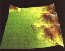
| Rice. 4. Examples of fragments of real areas of the earth's surface obtained at the levels of detail DTED2 (left) and DTED4 (right) | |
By artificially increasing the aperture of the on-board antenna, the main principle of which is the coherent accumulation of reflected radar signals over the synthesis interval, it is possible to obtain high angular resolution. In modern systems, resolution can reach tens of centimeters when operating in the centimeter wavelength range. Similar range resolution values are achieved through the use of intrapulse modulation, for example, linear frequency modulation (chirp). The antenna aperture synthesis interval is directly proportional to the flight altitude of the SAR carrier, which ensures that the shooting resolution is independent of altitude.
Currently, there are three main modes of surveying the earth's surface: overview, scanning and detailed (Fig. 1). In the survey mode, surveying of the earth's surface is carried out continuously in the acquisition band, while lateral and front-lateral modes are separated (depending on the orientation of the main lobe of the antenna radiation pattern). The signal is accumulated over a period of time equal to the calculated interval for synthesizing the antenna aperture for the given flight conditions of the radar carrier. The scanning shooting mode differs from the survey mode in that shooting is carried out over the entire width of the viewing swath, in stripes equal to the width of the capture swath. This mode is used exclusively in space-based radars. When shooting in detailed mode, the signal is accumulated over an increased interval compared to the overview mode. The interval is increased by moving the main lobe of the antenna radiation pattern synchronously with the movement of the radar carrier so that the irradiated area is constantly in the shooting area. Modern systems make it possible to obtain images of the earth's surface and objects located on it with resolutions of the order of 1 m for overview and 0.3 m for detailed modes. The Sandia company announced the creation of an SAR for tactical UAVs, which has the ability to survey with a resolution of 0.1 m in a detailed mode. The resulting methods of digital processing of the received signal, an important component of which are adaptive algorithms for correcting trajectory distortions, have a significant impact on the resulting characteristics of SAR (in terms of surveying the earth's surface). It is the inability to maintain a rectilinear trajectory of the carrier for a long time that does not allow obtaining resolutions comparable to the detailed mode in continuous overview shooting mode, although there are no physical restrictions on resolution in overview mode.
The inverse aperture synthesis (ISA) mode allows the antenna aperture to be synthesized not due to the movement of the carrier, but due to the movement of the irradiated target. In this case, we may not be talking about forward motion, characteristic of ground-based objects, but about pendulum motion (in different planes), characteristic of floating equipment swaying on the waves. This capability determines the main purpose of IRSA - detection and identification of marine objects. The characteristics of modern IRSA make it possible to confidently detect even small-sized objects, such as submarine periscopes. All aircraft in service with the Armed Forces of the United States and other countries, whose missions include patrolling the coastal zone and water areas, are capable of filming in this mode. The characteristics of the images obtained as a result of shooting are similar to those obtained as a result of shooting with direct (non-inverse) aperture synthesis.
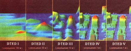
The interferometric survey mode (Interferometric SAR - IFSAR) allows you to obtain three-dimensional images of the earth's surface. At the same time, modern systems have the ability to conduct single-point shooting (that is, use one antenna) to obtain three-dimensional images. To characterize image data, in addition to the usual resolution, an additional parameter is introduced, called height accuracy, or height resolution. Depending on the value of this parameter, several standard gradations of three-dimensional images (DTED - Digital Terrain Elevation Data) are determined:
DTEDO........................900 m
DTED1.........................90m
DTED2........................ 30m
DTED3.........................10m
DTED4........................ Zm
DTED5........................1m
The type of images of an urbanized area (model), corresponding to different levels of detail, is presented in Fig. 3.
Levels 3-5 received the official name of “high resolution data” (HRTe-High Resolution Terrain Elevation data). The location of ground objects in images of levels 0-2 is determined in the WGS 84 coordinate system, the height is measured relative to the zero mark. The coordinate system for high-resolution images is currently not standardized and is under discussion. In Fig. Figure 4 shows fragments of real areas of the earth's surface obtained as a result of stereo photography with different resolutions.
In 2000, the American Space Shuttle, as part of the SRTM (Shuttle Radar Topography Mission) project, the goal of which was to obtain large-scale cartographic information, carried out interferometric surveys of the equatorial part of the Earth in the band from 60° N. w. to 56° south sh., resulting in a three-dimensional model of the earth's surface in DTED2 format. Is the NGA HRTe project being developed in the USA to obtain detailed 3D data? within which images of levels 3-5 will be available.
In addition to radar surveying of open areas of the earth's surface, airborne radar has the ability to obtain images of scenes hidden from the eyes of the observer. In particular, it allows you to detect objects hidden in forests, as well as those located underground.
Penetrating radar (GPR, Ground Penetrating Radar) is a remote sensing system, the operating principle of which is based on the processing of signals reflected from deformed or different in composition areas located in a homogeneous (or relatively homogeneous) volume. The earth's surface probing system makes it possible to detect voids, cracks, and buried objects located at different depths, and to identify areas of different densities. In this case, the energy of the reflected signal strongly depends on the absorbing properties of the soil, the size and shape of the target, and the degree of heterogeneity of the boundary regions. Currently, GPR, in addition to military applications, has developed into a commercially viable technology.
Probing of the earth's surface occurs by irradiation with pulses with a frequency of 10 MHz - 1.5 GHz. The irradiating antenna can be located on the earth's surface or located on board an aircraft. Some of the radiation energy is reflected from changes in the subsurface structure of the earth, while most of it penetrates further into the depths. The reflected signal is received, processed, and the results of the processing are displayed on the display. As the antenna moves, a continuous image is generated that reflects the state of the subsurface soil layers. Since reflection actually occurs due to differences in dielectric constants of different substances (or different states of one substance), probing can detect a large number of natural and artificial defects in a homogeneous mass of subsurface layers. The depth of penetration depends on the condition of the soil at the irradiation site. The decrease in signal amplitude (absorption or scattering) largely depends on a number of soil properties, the main of which is its electrical conductivity. Thus, sandy soils are optimal for probing. Clayey and very moist soils are much less suitable for this. Probing of dry materials such as granite, limestone, and concrete shows good results.
The resolution of sensing can be improved by increasing the frequency of the emitted waves. However, an increase in frequency has a negative effect on the radiation penetration depth. Thus, signals with a frequency of 500-900 MHz can penetrate to a depth of 1-3 m and provide a resolution of up to 10 cm, and with a frequency of 80-300 MHz they penetrate to a depth of 9-25 m, but the resolution is about 1.5 m.
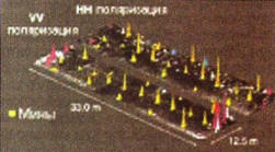
The main military purpose of subsurface sensing radar is to detect mines. At the same time, a radar installed on board an aircraft, such as a helicopter, allows you to directly open maps of minefields. In Fig. Figure 5 shows images obtained using a radar installed on board a helicopter, reflecting the location of anti-personnel mines.
An airborne radar designed to detect and track objects hidden in forests (FO-PEN - FOliage PENetrating) allows you to detect small objects (moving and stationary) hidden by tree crowns. Shooting objects hidden in forests is carried out similarly to regular shooting in two modes: overview and detailed. On average, in survey mode, the acquisition bandwidth is 2 km, which makes it possible to obtain output images of areas of the earth's surface 2x7 km; in detailed mode, surveying is carried out in 3x3 km sections. The shooting resolution depends on the frequency and varies from 10 m at a frequency of 20-50 MHz to 1 m at a frequency of 200-500 MHz.
Modern methods of image analysis make it possible to detect and subsequently identify objects in the resulting radar image with a fairly high probability. In this case, detection is possible in images with both high (less than 1 m) and low (up to 10 m) resolution, while recognition requires images with a sufficiently high (about 0.5 m) resolution. And even in this case, we can talk for the most part only about recognition by indirect signs, since the geometric shape of the object is very distorted due to the presence of a signal reflected from the foliage, as well as due to the appearance of signals with a frequency shift due to the Doppler effect that occurs in as a result of leaves swaying in the wind.
In Fig. 6 shows images (optical and radar) of the same area. Objects (a column of cars), invisible on an optical image, are clearly visible on a radar image, however, it is impossible to identify these objects, abstracting from external signs (movement on the road, distance between cars, etc.), since at this resolution information about The geometric structure of the object is completely absent.
The detail of the resulting radar images made it possible to put into practice a number of other features, which, in turn, made it possible to solve a number of important practical problems. One of these tasks includes tracking changes that have occurred on a certain area of the earth's surface over a certain period of time - coherent detection. The length of the period is usually determined by the frequency of patrols in a given area. Tracking of changes is carried out based on the analysis of coordinate-wise combined images of a given area, obtained sequentially one after another. In this case, two levels of analysis detail are possible.

|
|
| Fig 5. Maps of minefields in three-dimensional representation when shooting in different polarizations: model (right), example of an image of a real area of the earth's surface with a complex subsurface environment (left), obtained using a radar installed on board a helicopter | |

|
|
| Rice. 6. Optical (above) and radar (below) images of an area with a convoy of cars moving along a forest road | |

|
|
The first level involves the detection of significant changes and is based on the analysis of amplitude readings of the image, which carry basic visual information. Most often, this group includes changes that a person can see by simultaneously viewing two generated radar images. The second level is based on the analysis of phase readings and allows you to detect changes invisible to the human eye. These include the appearance of traces (of a car or a person) on the road, changes in the state of windows, doors (“open - closed”), etc.
Another interesting SAR capability, also announced by Sandia, is radar video. In this mode, the discrete formation of the antenna aperture from section to section, characteristic of the continuous survey mode, is replaced by parallel multi-channel formation. That is, at each moment of time, not one, but several (the number depends on the tasks being solved) apertures are synthesized. A kind of analogue to the number of apertures formed is the frame rate in regular video shooting. This feature allows you to implement the selection of moving targets based on the analysis of received radar images, applying the principles of coherent detection, which is inherently an alternative to standard radars that select moving targets based on the analysis of Doppler frequencies in the received signal. The effectiveness of implementing such moving target selectors is highly questionable due to significant hardware and software costs, so such modes will most likely remain nothing more than an elegant way to solve the selection problem, despite the emerging opportunities to select targets moving at very low speeds (less than 3 km/ h, which is not available to Doppler SDC). Direct video recording in the radar range is also not currently used, again due to high performance requirements, so there are no operating models of military equipment that implement this mode in practice.
A logical continuation of improving the technology of surveying the earth's surface in the radar range is the development of subsystems for analyzing the received information. In particular, the development of systems for automatic analysis of radar images that make it possible to detect, isolate and recognize ground objects within the survey area is becoming important. The difficulty of creating such systems is associated with the coherent nature of radar images, the phenomena of interference and diffraction in which lead to the appearance of artifacts - artificial glare, similar to those that appear when irradiating a target with a large effective scattering surface. In addition, the quality of the radar image is somewhat lower than the quality of a similar (in terms of resolution) optical image. All this leads to the fact that effective implementations of algorithms for recognizing objects in radar images do not currently exist, but the amount of work carried out in this area, certain successes achieved recently, suggest that in the near future it will be possible to talk about intelligent unmanned reconnaissance vehicles that have the ability to assess the ground situation based on the results of analyzing information received by their own on-board radar reconnaissance equipment.
Another direction of development is integration, that is, coordinated integration with subsequent joint processing of information from several sources. These can be radars that survey in various modes, or radars and other reconnaissance means (optical, IR, multispectral, etc.).
Thus, modern radars with synthetic antenna aperture make it possible to solve a wide range of problems associated with conducting radar surveys of the earth’s surface, regardless of the time of day and weather conditions, which makes them an important means of obtaining information about the state of the earth’s surface and the objects located on it.
Foreign Military Review No. 2 2009 P.52-56