Ways to improve the quality of PCM parts during vacuum forming. Establishing the reasons for the formation of porosity in the manufacture of Tsulagi PCM, vacuum covers and drainages
dx.doi.org/ 10.18577/2307-6046-2016-0-6-8-8
ESTABLISHING THE REASONS FOR POROSITY FORMATION DURING THE MANUFACTURE OF PCM
It is known that porosity in polymer composite materials (PCMs) has a significant impact on the strength properties of products operating under bending, compressive and shear loads. Currently, at FSUE “VIAM”, work on the creation of pore-free PCMs obtained by autoclave and non-autoclave molding methods is carried out in accordance with the “Strategic directions for the development of materials and technologies for their processing for the long term until 2030” (13.2. “Structural PCMs”) . The purpose of this work is to identify the main sources of porosity formation during the production of PCM using various methods. Using flat tested samples assembled from moistened prepregs and molded in an autoclave or under vacuum, it was found that the main source of porosity is the moisture contained in the binder and reinforcing fillers. Data from a study of the possibility of producing carbon fiber plastics by vacuum molding from prepregs obtained using solution technology with physical and mechanical properties equal to the properties of prepregs obtained by autoclave molding, including porosity, are presented. Recommendations and methods for getting rid of moisture during the preparation and manufacture of products are given.
Introduction
The structure of polymer composite materials (PCMs) consists of three components: reinforcing filler, binder (matrix) and pores. The reinforcing filler perceives the loads acting on the product, the binder binds together the individual fibers of the filler and redistributes the loads inside the product, and the pores “harm” the joint work of the other two components of the composite, reducing the resistance to compressive and shear loads and thereby reducing the performance of the structure. The manufacture of products from PCM by vacuum molding has been known for a long time and is widely used due to the simplicity and low cost of the process - however, only in the manufacture of non-strength parts, while manufacturers did not pay attention to the fiber-binder ratio and the presence of porosity in the finished products. The use of an autoclave when molding products from PCM made it possible to reduce the pore content to 1-2% due to a pressure of 6-7 at (0.6-0.7 MPa), so manufacturers in this case did not pay much attention to the porosity formed in this case , since the properties of the products met the specified requirements. However, with the transition to non-autoclave (without using high pressure) molding methods, additional research and development is necessary to ensure the same porosity (1-2%):
It was necessary to understand the reasons for the formation of porosity;
Find a solution for obtaining non-porous composites.
There are many sources of pore formation in composites. The mechanism of pore formation depends on the technology used. When products are manufactured using autoclave molding, pores formed during the curing process during high-pressure molding remain in the material in small quantities. When vacuum molding prepregs at significantly lower pressure than in an autoclave, obtaining parts with low porosity (1-2%) becomes a difficult task. To solve it, it is necessary first of all to understand the mechanism of pore formation. From an economic point of view, the transition from autoclave molding to vacuum molding can significantly reduce capital investments, increase energy efficiency, and eliminate the need to use expensive nitrogen. At the same time, restrictions on the size of manufactured parts are also removed.
Since the creation of glass fillers (since 1946), and then carbon-, boron- and organo-fibers (since 1970), FSUE VIAM has been working on the development and implementation of PCM based on them into aviation and rocket technology. Currently, work is being carried out in accordance with the strategic directions for the development of materials and technologies for their processing for the long term until 2030.
Different authors interpret the reasons for the formation of porosity in composites in different ways: some believe that porosity is formed from the remnants of air and volatile products captured during the manufacture of prepregs, others explain this by the presence of moisture found in binders and fillers, and others suggest that pores are formed from from both.
This article is devoted to the issue of considering the reasons for the formation of porosity in PCM and finding solutions for obtaining non-porous plastics.
Materials and methods
Autoclave and vacuum molding of prepregs
To better understand the reasons for the formation of pores in prepregs and control the formation of defects in parts manufactured abroad from OOA prepregs (out-of-autoclave), the mechanism of pore formation depending on the moisture content in the binder was studied. Uncured OOA prepreg based on an epoxy binder of the MTM 44-1 brand and a carbon filler of the CF 5804A brand from Advanced Composites Group (UK) was pre-moistened at a relative humidity of 70; 80 and 90% and temperature 35°C. 16-layer slabs measuring 203×292 mm with a quasi-isotropic reinforcement structure laid out from this prepreg were molded: one set under vacuum, and the other in an autoclave under pressure
5 at (0.5 MPa). We also made control samples, kept at the same temperature, but without moisture saturation to eliminate the possibility of pore formation from heating. One set of these plates was also molded in an autoclave under 5 atm (0.5 MPa) pressure, and the other was molded only under vacuum. Clean binder films were saturated with moisture for subsequent mass loss testing using thermogravimetric analysis (tracking rate 15°C/min). This weight loss was attributed to the moisture content of the binder, which was measured by Fisher coulometric analysis using a Mettler Toledo C-20 with a DO308 oven.
Due to the nature of vacuum formed prepregs, moisture in the binder has been considered a major cause of pore formation. The theoretical basis of the pore formation model follows from the assumption that pores grow through the diffusion of water from the surrounding binder. The driving forces of this process are temperature and pressure, and diffusion can promote both pore growth and pore dissolution depending on the solubility of moisture in the binder and the concentration gradient. Pore growth begins when the pressure inside the pore exceeds the hydrostatic pressure in the surrounding binder. Pores containing air collapse under pressure, but when they contain water, the water vapor pressure will increase exponentially as the temperature rises, causing the pores to stabilize and grow. The governing equations for selected mass diffusion bubble growth determine the pore diameter d mm and the driving force for pore growth β:
Where D- diffusion coefficient of water in the binder, mm 2 /h; t- duration of the process, s; C bulk - water concentration inside the binder, g/mm 3 ; C void - water concentration on the surface of the pores, g/mm 3 ; Pg- gas density, kg/m3.
The work provides a calculation of the growth of pore diameter depending on relative humidity, which increases exponentially (Fig. 1). It can be seen that due to the increased pressure during autoclave molding, the condition WITH void<WITH bulk is not performed and pores should not form and grow.
Rice. 1. Pore diameter for vacuum and autoclave molding depending on relative humidity (calculated values)
In order to compare the data obtained using the predicted model with the experimentally determined pore content, the pore diameters calculated from the model were converted into pore volume content. Using the pore diameters obtained from the model and the measured pore content, the volume of binder required to form one pore of a given diameter was obtained. It must remain constant for a given binder:
[% (vol.)], (3)
Where V m- volume of the unit matrix used to scale the results obtained using the model, mm 3.
In Fig. Figure 2 shows the measured pore content versus relative humidity along with the calculated values from the diffusion model.
Rice. 2. Calculated and experimental values of pore volume content
To validate the moisture model, thermogravimetric analysis results were compared with binder moisture content measured by Fischer titration. The values of the mass moisture content in the binder are equivalent to the values of the total mass loss when performing thermogravimetric analysis. This confirmed the assumption that in this case, volatile substances do not have a significant effect on pore growth; only moisture in the binder does. Thus, any volatile substances contained in the binder are in negligible quantities, and their contribution to the formation of pores can be neglected. In addition, the vacuum channels effectively remove air from the prepreg tested, and there is no indication that the observed pores can be attributed to “trapped” air and volatiles. We exclude these two potential sources of pores, leaving dissolved moisture as the only source, which justifies the use of the considered model to predict the formation of pores.
Although the amount of moisture in the prepreg appears relatively small when expressed in terms of mass content, its mole fraction is much higher, and water vapor can potentially occupy a large volume. This indicates that dissolved moisture may be the source of pore formation, since 1 liter of water under vacuum turns into 1000 liters of steam. Therefore, in order to obtain non-porous products by vacuum molding of prepregs, it is necessary to carefully control the humidity of the room during the laying of the layers to prevent the binder from collecting moisture. The work shows the sensitivity of the vacuum method to moisture content. A relative humidity of 45% corresponds to a mass moisture content in the binder of ~0.25%. Typically the binder supplied contains (0.24 ± 0.03)% moisture, which is slightly higher than the amount of moisture that can be controlled in atmospheric pressure molding.
If the binder is unpacked for 24 hours in a room at a relative humidity of (50±5)%, then the moisture content in it increases to (0.30±0.01)%. Production of large parts often requires several days of cutting and laying out prepreg. Therefore, to obtain high-quality parts using the non-autoclave method, it is necessary to control the humidity inside the workroom. Assembly must be carried out in a room in which not only the temperature, but also the relative humidity of the air is set and maintained.
The authors carried out work to study the possibility of using vacuum molding of prepregs obtained using solution technology in order to produce PCM with a binder content similar to that obtained during autoclave molding and thereby obtaining minimal porosity. For this purpose, we used prepregs based on equal-strength fabric from Porcher (art. 3692) with a surface density of 200 g/m2, impregnated with a solution epoxy binder EDT-69N(M) on an UPST-1000M installation, with a binder content of 39-40% and volatile 2 ±0.3%. The solvent for the binder was a mixture of alcohol and acetone in a ratio of 2:1. To achieve this goal, it was necessary to obtain a binder content in the plastic similar to that obtained during autoclave molding. We assembled two types of flat panels measuring 300×300 mm, of which two samples were molded under vacuum, and the other two were molded in an autoclave. Each sample consisted of 17 layers, with the first sample being assembled from 17 layers of prepreg, and the second from prepregs alternating with dry layers of Porcher fabric (art. 3692). T-45(p)-76 fiberglass fabric was used as absorbent layers. Two samples were molded in an autoclave according to the mode recommended by the developers of the material, and the other two were molded under a vacuum bag in a heating cabinet according to a mode different from the autoclave mode. To prevent the binder from leaking out from the ends, the latter were protected with a layer of sealing tape.
In this case, the molding mode must be selected in such a way that before gelling of the binder begins, all steam-air inclusions and volatile products, as well as excess binder in the prepregs, are removed. In this case, to remove volatile and gaseous inclusions, appropriate conditions must be created, such as low viscosity of the binder, temperature and the presence of a pressure drop of the molded package, which the escaping gases, as well as the binder, could overcome. This also includes the permeability value of the prepreg filled with a viscous binder. The process of removing volatile products must be accompanied by the process of filling with a binder the voids that exist and are formed due to the removed volatiles. Filling of voids with a binder will be carried out due to both the pressure created during evacuation and due to capillary forces. In this case, devolatilization will first begin with the first top layer of prepreg adjacent to the release porous breathable film. Then from the second layer adjacent to it, etc. until the last layer.
In autoclave molding, residual volatiles not removed by vacuum will be molded into the plastic in the form of bubbles using the pressure created and will be smaller the higher the molding pressure. If molding is carried out only due to vacuum pressure, then those volatiles that remain in the prepregs will increase their volume, and the higher the vacuum and temperature, the greater the volume. Therefore, to obtain a material with minimal porosity, it is necessary to achieve complete removal of volatiles using appropriate technological methods. In this case, volatiles located in the upper layers of the prepreg package are removed first and quite easily, since the resistance of the small thickness of the viscous binder is low for them. The volatiles located in the lower layers of the package must overcome significant resistance, firstly, from the pressure created by the vacuum, and, secondly, from the binder, which has a viscosity many times greater than the viscosity of gaseous volatiles.
results
According to Darcy's law, for porous materials, which include reinforcing materials, the filtration rate v directly proportional to permeability and pressure drop and inversely proportional to the viscosity of the liquid or gas and the thickness of the package:
Where K- structure permeability coefficient, D (Darcy); η - viscosity of liquid or gas, Pa s; D R- pressure drop, MPa; N- package thickness, cm.
To remove excess binder and volatile products from the prepreg package, dry (unimpregnated) fabric of the same brand was used, which was placed between the layers of prepreg and ensured drainage of volatile products during vacuuming. By creating pressure and temperature, the dry fabric was filled with a binder from nearby prepreg layers at the time of molding. The finished carbon fiber panels were cut into samples to determine the physical and mechanical characteristics. From the same batch of prepregs, similar panels were assembled, molded in an autoclave, samples of which were also tested.
From formula (4) it is clear that the greater the viscosity and thickness of the bag, the lower the filtration speed, and also the lower the permeability, the lower the speed.
Devolatilization is carried out at elevated temperatures, when the viscosity of the binder decreases and volatiles (such as acetone and alcohol residues) pass into a gaseous state. The viscosity of acetone at a temperature of 75°C is 0.228 mPa s, of alcohol: 0.471 mPa s, and of air at 20°C: 0.018 mPa s. The viscosity of the binder at a temperature of 80-90°C is 0.4-0.6 mPa s, which naturally will inhibit the movement of escaping gas inclusions.
From the above it follows that the greater the thickness of the product and the lower the permeability coefficient, the more difficult it is to remove volatiles from the lower layers of the prepreg. One of the technological methods is the so-called stage-by-stage assembly of a package of prepregs with evacuation at temperature after laying out several layers, which makes it possible to remove the main part of the volatiles before final molding. Using this method, Boeing manufactured a stabilizer panel from carbon prepregs using Cycom 5320 binder, thereby obtaining a material porosity of ˂1%. However, this method assumes an equal content of the binder in the prepreg and the product, and this can be achieved in installations that provide dosed application of the binder melt. When manufacturing PCM based on prepregs produced using solution technology, the weight content of the binder in the prepreg is, as a rule, greater than it should be in the product. Therefore, porous absorbent layers are used to remove excess binder during autoclave molding. When manufacturing thick-walled structures, sometimes dry layers of fabric are introduced into the structure of the assembled prepreg package, alternating with several layers of prepreg, depending on the initial content of the binder in the prepreg and the required content of the binder in the finished product. Such layers, being a good drainage material, ensure the removal of volatiles from nearby prepreg layers and absorb excess binder from them.
Samples were cut from the finished carbon fiber plastic plates to determine the density using hydrostatic weighing, as well as bending and shear strength, water absorption by boiling, and strength after boiling. Based on the results of hydrostatic determination of density and calculation of theoretical density, based on the thickness of the plastic monolayer, the porosity of the resulting samples was calculated using the formula:
where γ is and γ t are the true and theoretical density of the plastic, respectively, g/cm 3 .
In terms of monolayer thickness, binder content, plastic density, porosity and water absorption (see table), the performance of samples without dry and with dry layers of fabric during vacuum molding are close to each other. It follows that vacuum molding is possible both from prepregs and in combination with dry layers. During autoclave molding, there is also virtually no difference between samples made from prepregs and prepregs with dry layers of fabric.
It should be especially noted that the use of absorbent layers and especially dry layers made it possible to obtain PCM with low porosity, close to the porosity obtained by autoclave molding (see table).
Properties of fabric-based carbon fiber reinforced plasticscompaniesPorcher(art. 3692) and binder
EDT-69N(M), manufactured by vacuum molding and in an autoclave
|
Monolayer thickness, |
Plastic density, g/cm 3 |
Porosity |
Water absorption |
Ultimate bending/shear strength, MPa |
|||||
|
in prepreg |
in plastic |
true |
calculated |
in original condition |
after boiling |
||||
|
Vacuum forming (average values) |
|||||||||
|
No dry layers |
|||||||||
|
With dry layers |
|||||||||
|
Autoclave molding (average values) |
|||||||||
|
No dry layers |
|||||||||
|
With dry layers |
|||||||||
The flexural strength, binder content and density of the CFRPs produced in the autoclave are similar, but it should be noted that the introduction of dry layers led to a slight increase in strength and density and a decrease in the binder content. This indicates that the introduction of dry layers promotes a more intensive removal of excess binder into the dry layers.
The samples produced by vacuum molding showed high bending strength of plastic with dry layers. However, the density of this plastic is slightly lower than that of the same samples made by autoclave molding. With regard to the flexural strength, density and binder content of samples consisting of prepregs alone, it can be assumed that the presence of absorbent layers with high permeability and absorption led to the removal of excess binder into these layers more than required, and the resulting voids in the plastic did not were filled with a binder, which is confirmed by the greater porosity in them. Therefore, when manufacturing products using the vacuum molding method, it is necessary to strictly select the number of absorbent layers into which part of the excess is absorbed, and the rest will be used to fill the voids formed when air-steam and volatile products are removed. But in this case, it is better to use the introduction of dry layers, strictly calculating their number.
Infusion molding of dry preforms
The transition to non-autoclave molding methods by impregnating a package of dry reinforcing filler, located in a hermetically sealed form, with liquid binders under pressure required, as well as molding prepregs under vacuum, research into the mechanism of pore formation in the resulting plastics. In autoclave or vacuum molding of prepregs, pore initiation and growth occurs during the curing cycle, while in liquid molding methods, the main source of porosity is considered to be "trapped" air. The microstructure of textile forms contains two types of pores with very different sizes: micropores (inside the fiber bundles) between the individual filler fibers and macropores, which are the empty space between the individual threads.
The heterogeneity of the structure causes the uneven flow of the binder during impregnation: the binder moves through large pores in accordance with Darcy's law under the influence of a pressure gradient, and through small pores (capillaries) - under the action of capillary forces. The uneven speed of movement of the binder through two different channels leads to the formation of double flow and two types of pores in the structure of the resulting plastics. The rapid flow of the binder through large pores leads to the formation of porosity inside the fiber bundles, where the speed of movement due to capillary pressure lags behind the speed of movement inside the large pores. If the speed of movement of the binder is low, then the air bubble is “locked” in the macropores, from where the binder, after filling them, is removed due to capillary forces into the micropores inside the fibers.
The works experimentally established that the formation of pores in the flow front correlates with a dimensionless quantity called the capillary number ( WITH a), which is the ratio of the viscosity of the binder to its surface tension:
where μ is the viscosity of the binder; u- flow rate of the binder; γ - surface tension of the binder; Q- wetting angle; m- porosity of the reinforcing filler.
The work investigated the effect of the binder supply rate on pore formation, relating them to the resulting capillary number. Three types of glass fiber-based reinforcing fillers were studied: chopped fiber mats, bidirectional and unidirectional fabrics. The work was carried out on samples measuring 350×250×3 mm with the injection of an epoxy binder with a surface tension of 35 mN/m and a viscosity of 0.1 Pa s. The injection rate varied from 6 to 18 ml/s. It was found that at low binder supply rates, capillary forces become dominant, drawing the liquid flow through bundles of fabric fibers, in which, if any, voids are formed, the minimum number of voids is formed. In this case, macrovoids are formed in the places where the fiber bundles of the warp fabric intertwine with the weft. At high flow rates, the binder passes mainly through the intersections of the warp and weft, forming a large number of microvoids in the interfiber gaps.
The formation of pores in polymer materials produced by infusion methods or pressure impregnation is affected not only by the air remaining in the filler, but also by the moisture contained in them and in the binders, as mentioned earlier, during vacuum molding of prepregs. Fabrics used for the manufacture of products using liquid molding technology, if they are in normal workshop conditions, always contain so-called capillary moisture in the areas of weaving of monofilaments in bundles, where the pore radius is ˂10 -5 cm. It is even more difficult to remove capillary moisture retained by the fabric , the smaller the capillary radius. Removing it requires additional energy consumption, so it is necessary to get rid of it before the impregnation process by drying at elevated temperatures. The air in the tissues is removed by vacuum, and to remove capillary moisture, heating to 70°C is required to convert it into steam under vacuum. Therefore, before carrying out the impregnation process, the fabric must be dried before the bag is assembled, and then vacuum-sealed under a sealing film. It is necessary to degas the binder to remove moisture and volatile substances before starting impregnation.
There are a large number of patents for the vacuum infusion method aimed at improving the quality of the resulting products. There is a known method for manufacturing products using vacuum infusion technology developed by EADS, according to which the working cavity where the preform is placed communicates with a container for the binder and a vacuum pump. The working cavity is formed by a semi-permeable membrane attached to the equipment using hermetically sealed seals. A gas-tight film is located on top of the membrane, also attached to the equipment using sealing seals, as a result of which a second cavity is formed between the membrane and the sealed film, hermetically separated from the external space, as well as the first (working) cavity associated with the vacuum pump. In this case, due to the semi-permeable membrane, an air connection is created between the first and second cavities. In the second cavity between the membrane and the gas-tight film there is a ventilation fabric intended for the directed movement of air and other volatile components passing from the working cavity through the membrane into the second cavity to the vacuum pump.
Discussion and conclusions
Based on numerous scientific literature sources used, the reasons for the formation of porosity during the molding of PCM products using both autoclave and non-autoclave methods have been established. The main source of porosity is moisture contained in binders and reinforcing fillers, which turns into steam when heated. The pores formed during autoclave molding are reduced in size due to excess pressure and, as a rule, porosity does not exceed 2-3% (vol.). When vacuum molding prepregs to obtain non-porous plastics, careful control of the humidity of storage areas and assembly of packages of dry reinforcing fillers and prepregs is required, as well as the use of prepregs with one-sided application of a binder. With infusion molding methods, the porosity of plastics is also affected by moisture and volatile substances in the binders, which must be thoroughly degassed before impregnation, as well as moisture contained in the fillers. Therefore, before assembling the package, the fillers must be dried, and the assembly of the package must be carried out in rooms with a humidity of no more than 45-50%; during the impregnation process, a deeper vacuum must be used to remove gaseous products remaining in the assembled preforms, using semi-permeable membranes. In addition, to obtain non-porous plastics, it is necessary to ensure uniform flow of the binder both through large channels between the threads and through the capillary gaps between the fibers of the threads to avoid the formation of the so-called “double flow”.
LITERATURE REFERENCE LIST
1. Kablov E.N. Innovative developments of the Federal State Unitary Enterprise “VIAM” of the State Scientific Center of the Russian Federation for the implementation of “Strategic directions for the development of materials and technologies for their processing for the period until 2030” // Aviation materials and technologies. 2015. No. 1 (34). pp. 3–33
2. Mikhailin Yu.A. Structural polymer composite materials. SPb.: Scientific principles and technologies. 2008. 822 p.
3. Brautman L. Destruction and fatigue. M.: Mir, 1978. 153 p.
9. Kablov E.N., Kondrashov S.V., Yurkov G.Yu. Prospects for the use of carbon-containing nanoparticles in binders for polymer composite materials // Russian Nanotechnologies. 2013. T. 8. No. 3–4. pp. 24–42.
10. Donetsky K.I., Kogan D.I., Khrulkov A.V. Properties of polymer composite materials made on the basis of woven preforms // Proceedings of VIAM: electron. scientific and technical magazine 2014. No. 3. Art. 05. URL: http://www..01.2016). DOI: 10.18577/2307-6046-2014-0-3-2-2.
11. Donetsky K.I., Khrulkov A.V., Kogan D.I., Belinis P.G., Lukyanenko Yu.V. Application of volume-reinforcing preforms in the manufacture of products from PCM // Aviation materials and technologies. 2013. No. 1. pp. 35–39.
12. Kablov E.N. Materials and chemical technologies for aviation technology // Bulletin of the Russian Academy of Sciences. 2012. T. 82. No. 6. pp. 520–530.
13. Kablov E.N., Grashchenkov D.V., Erasov V.S., Anchevsky I.E., Ilyin V.V., Walter R.S. Stand for testing large-sized structures made of PCM at the GCKI climate station // Collection of articles. report IX International scientific conf. on hydroaviation "Gidroaviasalon-2012". 2012. pp. 122–123.
14. Khrulkov A.V., Dushin M.I., Popov Yu.O., Kogan D.I. Research and development of autoclave and non-autoclave technologies for molding PCM // Aviation materials and technologies. 2012. No. S. pp. 292–301.
15. Dushin M.I., Khrulkov A.V., Mukhametov R.R. Selection of technological parameters for autoclave molding of parts from polymer composite materials // Aviation materials and technologies. 2011. No. 3. pp. 20–26.
27. Dushin M.I., Khrulkov A.V., Platonov A.A., Akhmadieva K.R. Non-autoclave molding of carbon fiber reinforced plastics based on prepregs obtained using solution technology // Aviation materials and technologies. 2012. No. 2. pp. 43–48.
38. Lykov A.V. Drying theory. M.: Energy, 1968. 472 p.
42. A method for producing fibrous composites by vacuum infusion and a device for implementing the method: Pat. 2480335 PU; publ. 04/27/13.
1. Kablov E.N. Innovacionnye razrabotki FGUP "VIAM" GNC RF po realizacii "Strategicheskih napravlenij razvitiya materialov i tehnologij ih pererabotki na period do 2030 goda" // Aviacionnye materialy i tehnologii. 2015. No. 1 (34). S. 3–33.
2. Mihajlin Yu.A. Konstrukcionnaye polimernye kompozicionnye materialy. SPb.: Nauchnye osnovy i tehnologi. 2008. 822 s.
3. Brautman L. Razrushenie i ustalost. M.: Mir, 1978. 153 s.
4. Void Content of Reinforced Plastic: ASTM D 2734-09. Standard by ASTM International. 2009. 3 p.
5. Tavares S.S., Michaud V., Manson J.A.E. Through thickness air permeability of prepregs during cure // Composites: Part A. 2009. V. 40. P. 1587–1596.
6. Thomas S., Nutt S.R. In situ estimation of though-thickness resin flow using ultrasound // Compos. Sci. Technol. 2008. 68:3093-8.
7. Tavares S.S., Michaud V., Manson J.A.E. Assessment of semi-impregnated fabrics in honeycomb sandwich structures // Composites: Part A. 2010. V. 41. P. 8–15.
8. Jackson K., Crabtree M. Autoclave quality composites tooling for composite from vacuum bag only processing // 47th International SAMPLE symposium. 2002. P. 800–807.
9. Kablov E.N., Kondrashov S.V., Yurkov G.Yu. Perspektivy ispolzovaniya uglerodsoderzhashhih nanochastic v svyazuyushhih dlya polimernyh kompozicionnyh materialov // Rossijskie nanotehnologii. 2013. T. 8. No. 3–4. S. 24–42.
10. Donetskij K.I., Kogan D.I., Hrulkov A.V. Svojstva polimernyh kompozicionnyh materialov, izgotovlennyh na osnove pletenyh preform // Trudy VIAM: elektron. nauch.-technich. zhurn. 2014. No. 3. St. 05. Available at: http://www.. DOI: 10.18577/2307-6046-2014-0-3-5-5.
11. Donetskij K.I., Hrulkov A.V., Kogan D.I., Belinis P.G., Lukyanenko Yu.V. Primenenie obemno-armiruyushhih preform pri izgotovlenii izdelij iz PKM // Aviacionnye materialy i tehnologii. 2013. No. 1. S. 35–39.
12. Kablov E.N. Materialy i himicheskie tehnologii dlya aviacionnoj tehniki // Vestnik Rossijskoj akademii nauk. 2012. T. 82. No. 6. S. 520–530.
13. Kablov E.N., Grashhenkov D.V., Erasov V.S., Anchevskij I.Je., Ilin V.V., Valter R.S. Stend dlya ispytaniya na klimaticheskoj stancii GCKI krupnogabaritnyh konstrukcij iz PKM // Sb. dokl. IX Mezhdunar. nauch. conf. po gidroaviacii "Gidroaviasalon-2012". 2012. S. 122–123.
14. Hrulkov A.V., Dushin M.I., Popov Yu.O., Kogan D.I. Issledovaniya i razrabotka avtoklavnyh i bezavtoklavnyh tehnologij formovaniya PKM //Aviacionnye materialy i tehnologii. 2012. No. S. S. 292–301.
15. Dushin M.I., Hrulkov A.V., Mukhametov R.R. Vybor tehnologicheskih parametrov avtoklavnogo formovaniya detalej iz polimernyh kompozicionnyh materialov // Aviacionnye materialy i tehnologii. 2011. No. 3. S. 20–26.
16. Wood J.R., Bader M.G. Void control for polymer-matrix composites (1) theoretical and experimental methods for determining the growth and collapse of gas bubbles // Compos. Manuf. 1994. V. 5 (3). P. 139–147.
17. Wood J.R., Bader M.G. Void control for polymer-matrix composites (1) theoretical and experimental evaluation of a diffusion model for the growth and collapse of gas bubbles // Compos. Manuf. 1994. V. 5 (3). P. 149–158.
18. Liu L., Zhang B., Wang D., Wu Z. Effects of cure cycle on void content and mechanical properties of composite laminates // Compos. Struct. 2006. V. 73. P. 303–309.
19. Liu L., Zhang B., Wu Z., Wang D. Effects of cure pressure induced voids on the mechanical strength of carbon/epoxy laminates // J. Mater. Sci. Technol. 2005. V. 21 (1). P. 87–91.
20. Olivier P., Cottu J.P., Ferret B. Effects of cure cycle pressure and voids on some mechanical properties of carbon/epoxy laminates // Composites. 1995. V. 26 (7). P. 509–515.
21. Huang H., Talreja R. Effects of void geometry on elastic properties of unidirectional fiber reinforced composites // Composites Science and Technology. 2005. V. 65. P. 1964–1981.
22. Costa M.L., Almeida S.F.M., Rezende M.C. The influence of porosity on the interlaminar shear strength of carbon/epoxy and carbon/bismaleimide fabric laminates // Composites Science and Technology. 2001. V. 61. P. 2101–2108.
23. Grunenfelder L.K., Nutt S.R. Void formation in composite prepregs – effect of dissolved moisture // Composites Science and Technology. 2010. V. 70. R. 2304–2309.
24. Kardos J.L., Dudukovic M.P., Dave R. Void growth and resin transport during processing of thermosetting-matrix composites // Adv. Polym. Sci. 1986. V. 80. P. 102–123.
25. Boey F.Y.C., Lye S.W. Void reduction in autoclave processing of thermoset composites part 1: high pressure effects on void reduction // Composites. 1992. V. 23 (4). P. 261–265.
26. Hayward J.S., Harris B. Effect of process variables on the quality of RTM mouldings // SAMPE J. 1990. V. 26 (3). P. 39–46.
27. Dushin M.I., Hrulkov A.V., Platonov A.A., Ahmadieva K.R. Bezavtoklavnoe formovanie ugleplastikov na osnove prepregov, poluchennyh po rastvornoj tehnologii // Aviacionnye materialy i tehnologii. 2012. No. 2. S. 43–48.
28. Lundstrom T.S., Gebart B.R., Lundemo C.Y. Void formation in RTM // The 49th annual conference. Session 16-F. Composite Institute of the Society of the Plastics Industry. 1992.
29. Patel N., Lee L.J. Effect of fiber mat architecture on void formation and removal in liquid composite molding // Polym. Compos. 1995. V. 16 (5). P. 386–399.
30. Patel N., Rohatgi V., Lee L.J. Modeling of void formation and removal in liquid composite molding. Part II. Model development // Polym. Compos. 1996. V. 17 (1). P. 104–114.
31. Chen Y.T., Davis H.T., Macosko C.W. Wetting of fiber mats for composite manufacturing: I. Visualization experiments. AlChE // J. Polym. Compos. 1995. V. 41 (10). P. 2261–2273.
32. Patel N., Rohatgi V., Lee L.J. Micro scale flow behavior and void formation mechanism during impregnation through a unidirectional stitched fiberglass mat // Polym. Eng. Sci. 1995. V. 35 (10). P. 837–851.
33. Rohatgi V., Patel N., Lee L.J. Experimental investigation of flow induced microvoids during impregnation of unidirectional stitched fiberglass mat // Polym. Compos. 1996. V. 17 (2). P. 161–170.
34. Ruiz E., Achim V., Bread J., Chatel S., Trouchu F. A fast numerical approach to reduce voud formation in liquid composite molding // The 8th International Conference on Flow Processes in Composite Materials (FPCM8). Douai. 2006. P. 251–260.
35. Bread J., Henzel Y., Trouch F., Gauvin R. Analysis of dynamic flow through porous media. Part I: Comparison between saturated and unsaturated flows in fibrous reinforcements // Polymer Composites. 2003. V. 24. No. 3. P. 409–421.
36. Lee G.W., Lee K.J. Mechanism of void formation in composite processing with woven fabrics // Polymer and Polymer Composites. 2003. V. 11. No. 7. P. 563–570.
37. Hayward J.S., Harris B. Effect of vacuum assistance in resin transfer molding // Compos. Manuf. 1990. V. 1 (33). P. 161–166.
38. Lykov A.V. Teoriya sushki. M.: Energiya, 1968. 472 s.
39. High-performance infusion system for VARTM fabrication: pat. 6964561 USA; publ. 11/15/05.
40. Method for making composite structures: pat. 6630095 US; publ. 07.10.03.
41. Method and device for producing fiber-reinforced components using an injection method: Pat. 1181149 EU; publ. 12/10/03.
42. Sposob izgotovleniya voloknistyh kompozitov vakuumnoj infuziej i ustrojstvo dlya osushhestvleniya sposoba: pat. 2480335 PU; publ. 04/27/13.
You can leave a comment on the article. To do this you need to register on the site.
Autoclave molding technology is used to produce multilayer products from prepregs. The method gets its name from the use of an autoclave, which allows the external part of the part to be processed at high pressure. Initially, the technology was used for fixing parts in the production of aircraft products. A prepreg or a package consisting of several layers is placed in the mold. Together with the mold, the prepreg is placed in a vacuum bag, where the pressure is gradually reduced. Vacuum bag forming is a method that involves curing the product by creating a pressure gradient relative to normal atmospheric pressure.
Autoclave molding steps:
- A specified number of prepreg layers are placed on the mold.
- Curing is carried out in an autoclave under high pressure and at high temperature.
- Cured products are subjected to processing: cleaning, finishing.
A vacuum bag is often used for autoclave curing. The main properties of the product are determined by the type of bag and the method of laying out the prepreg.
Specifics of autoclave molding technology
The use of a vacuum bag makes it possible to obtain high-quality fiberglass products with low porosity. The surface of the products is of high quality. Using the technology, large-sized products can be molded. A special feature of the method is the ability to obtain parts of uniform thickness.
The technology has its drawbacks: the cost of the method is high, production is labor-intensive, and is not suitable for mass production of parts. But the effectiveness of the technology is undeniable when producing parts from lightweight fiberglass.
It is possible to reduce the cost of the production process and parts manufactured using the method by automating individual operations and mechanizing the process. For vacuum bags, it is worth choosing other materials, which will also affect the cost of the products. Silicone rubber bags can be used repeatedly. During the production process, it is important to accurately select the temperature and pressure levels, since these parameters affect the properties of the part.
It is worth remembering that the use of vacuum bags is associated with a fire hazard. Failure to comply with safety requirements may result in explosions and fires during the autoclave molding process. To ensure safety, an inert gas atmosphere containing nitrogen can be used.
When producing products from polymer composite materials, it is necessary to pay special attention to the choice of production technology. Not only the economic component, but also the quality of the final product depends on this decision.
Our company’s specialists will help you with the choice of production technology, as well as select the necessary materials and equipment.
Call us and you will have no doubt about the correctness of your decision!
HAND MOLDING
The production of products by manual (contact) molding is the basic process for the production of products from polymer composite materials. The advantages of this method include the simplicity of the technology and minimal costs for preparing and carrying out the molding process (there is no need to purchase expensive equipment). The disadvantage of this method is the low quality of the final product - high resin content, and, as a result, high weight and low strength characteristics. This method has become widespread in the production of large-sized products, which do not have high requirements for physical and mechanical properties. Basically, the technology is applicable to single products or small-scale production.
In this molding process, pre-cut reinforcement material is placed into a mold treated with a release agent and coated with gelcoat to create a protective layer for the final product. After this, the reinforcing material is impregnated with the prepared epoxy composition (resin and hardener) manually - using a brush or rollers. Before curing, it is necessary to “roll” the entire surface of the product with a sealing roller. If this is not done, then the final product may contain air bubbles that negatively affect its quality. After curing, the product is removed from the mold and further mechanical processing occurs.
VACUUM FORMING
Production using vacuum forming technology ensures a higher quality of the final product compared to the classic manual method. The main difference from the contact method is that after impregnation of the reinforcing material with an epoxy system, a vacuum bag is attached to the equipment using a sealing cord. Due to the vacuum created by the vacuum pump, air bubbles and excess resin are removed from the laminate. Otherwise, the process is identical to the manual molding method. The advantages of this method include the simplicity of the technology and minimal costs for preparing and carrying out the molding process (there is no need to purchase expensive equipment). Higher quality of the final product compared to the contact method. The disadvantage of this technology is the limited time for creating a vacuum bag and, as a result, high requirements for personnel qualifications.
VACUUM INFUSION
The technology for producing products using the vacuum infusion method has become widespread among manufacturers of products made from polymer composite materials. The main reasons for the popularization of this technology are the low cost of equipment (compared to the autoclave method and RTM technology), as well as the high quality of the final product and the ability to mold large-sized products with relatively little time. Vacuum infusion is a closed molding process. It is pre-laid onto the prepared equipment cut reinforcing material. The thickness of the final product is set immediately, at the stage of laying reinforcing fabrics, by laying out the required number of layers of fabric or using sandwich structures - foam plastic or honeycomb panels. A set of auxiliary consumables is placed together with the reinforcing material. The future product is covered with a vacuum film and attached to the flanges of the equipment using a sealing cord. A vacuum pump is connected to the vacuum bag through the installed vacuum port to ensure that the bag is assembled correctly and that there are no air leaks. Detected leaks must be eliminated at this stage, since after supplying the resin the process will be irreversible. Thanks to the created vacuum, the pre-degassed resin enters the vacuum bag through a vacuum tube. When using a conductive mesh, the resin most quickly and evenly impregnates the layers of reinforcing material. After all layers have been impregnated, the resin supply line is shut off and the vacuum is left on. This eliminates the presence of air inclusions in the final product. Depending on the type of epoxy resin and the required design, the product may be further cured in an oven or autoclave. The line of materials for vacuum infusion supplied by our company includes high-temperature consumables for post-curing processes. When using this technology, a high-quality final product is ensured due to the high-quality ratio of resin and reinforcing material. Air inclusions and excess are removed from the reinforcing material by constantly maintaining a vacuum. The process is completely reversible until the resin is supplied. Therefore, there is no time limit when assembling the vacuum bag.
INJECTION INTO MOLD (RTM process)

RTM process (Resin Transfer Molding) is the process of feeding (injecting) resin into a closed mold. Classic RTM involves the use of aluminum dies (lower part) and punch (mating part). When produced using RTM technology, a glossy surface is ensured on both sides. Pre-cut dry reinforcing material is placed in the prepared mold. The closure of the mold is fixed either with fastening bolts, or the closure of the mold occurs in a press. In the latter option, it is advisable to use a press with heating plates to uniformly heat the binder during the resin injection process. To supply the resin, special injection equipment is used, which ensures high-quality mixing of the components, heating of the supply lines and the required resin pressure at the outlet. After opening the mold, the product is sent to the mechanical processing area. The advantage of this technology is the ability to produce products of various geometric shapes in one injection, which eliminates the need for gluing highly loaded elements, and, as a result, increases the physical and mechanical properties of the product. This technology is applicable for medium-scale production of highly loaded structural elements.
AUTOCLAVE MOLDING

The process of producing parts using the autoclave method takes place at high pressure and temperature, which makes it possible to obtain products of high strength. Autoclave technology has received its main development thanks to the use of carbon fiber structures in the aerospace sector and aircraft manufacturing, due to the low weight and high physical and mechanical properties of the final products. A pre-cut prepreg or a multilayer package of prepreg based on carbon fibers is placed in a mold, to which using a heat-resistant The sealing harness is attached to a vacuum bag. By using a vacuum pump, a vacuum is created in the vacuum bag and air inclusions are removed from the laminate. Next, the product is loaded into the autoclave on a special trolley moving on rails. Without turning off the vacuum, excess pressure and heating are created in the autoclave to the curing temperature of the prepreg. The use of a vacuum pump allows the porosity of the laminate to be reduced to a minimum, which guarantees high quality of the final product. The use of autoclave technology allows the production of large-sized products to which the highest quality requirements are applied. This method is of little use for large-scale production and is more widely used in the production of small batches of high-quality products. The disadvantage of the autoclave method is the high cost of the autoclave itself, as well as the presence of manual labor, which requires highly qualified personnel.
FILAMENT WINDING

Filament winding technology involves depositing fibers impregnated in a resin bath or winding prepreg onto a rotating mandrel to precisely meet specific requirements. Special software is responsible for the correct winding of fibers, with the help of which a working cycle is created. Bobbins with roving are installed in a special rack (creel), in accordance with the requirements for the width of the wound tape. The fibers are formed into a ribbon and placed in a resin bath, where they are impregnated with an epoxy binder (or any other resin system). At the exit from the impregnation bath, excess resin is removed from the impregnated material and returned to the bath. The amount of binder in the fibers, as well as the tension of the threads, is adjusted with high precision, in accordance with the technical requirements of the Customer. The impregnated dies are wound onto a rotating mandrel at different angles. Then the thickness of the created product is set. The ability to fully control the winding process and set a large number of parameters guarantees high quality of the final product. Using filament winding technology, rotating bodies of various shapes are created: cylindrical, conical, ogival. On winding machines it is possible to produce cylinders, containers and tanks for water and liquefied gas; pipeline production; manufacturing of parts for the aerospace and aviation sector. When using this technology for the production of high-pressure cylinders, multi-spindle versions of machines are used to ensure large-scale production.
PULTRUSION

Pultrusion is a process used to produce a continuous reinforced composite material with a constant cross-section.
As a standard, glass roving (fiberglass mat, glass veil) is used as a reinforcing material, and polyester resin is used as a binder. The choice of these materials is due to their low cost, which is of fundamental importance in the continuous production of profiles (rods, pipes, plates, angles, boxes, etc.).
Continuous glass roving (mat, thread, fabric or voile) is unwound from the creel and placed in a resin bath. The design of the bath ensures thorough impregnation of the reinforcing material. The resin may contain fillers or additives, depending on the requirements of the final product. The impregnated reinforcing material passes through special rollers at the exit of the bath to remove excess resin. Next, the material passes through a heated forming die to obtain the required geometry of the product. In the die, polymerization of the profile occurs due to heating carried out by electric heating elements. The pulling device (grips) ensures continuous pulling of the profile from the die. The resulting product is cut using a saw (cutter) installed at the end of the pultrusion line. The speed of the process, the force of the pulling devices, the heating of the die, as well as the length of the cut product are regulated and set using the control system.
Pultrusion is a high-volume production of various profiles of a constant cross-section. The advantages of this technology are high speed and continuity of production, low cost of binders, high corrosion resistance and low weight (compared to metals), low thermal coefficient of linear expansion and good electrical insulating properties. The disadvantages of this technology include the high cost of the die and, accordingly, the high cost of the final product for a small series, as well as limited production - to produce a product of a different geometry or size, a new die is required.
The Modern Polymer Technologies company offers a full range of materials and equipment for implementing these technologies in your production.
To improve the quality of products, the vacuum-autoclave molding method is used. The molding process is carried out under the influence of high pressures of compressed gases or liquids on the molded product, which is vacuumized on the mold
Rice. 2.13. Scheme of molding in autoclaves and hydroclaves:
/ - autoclave; 2 - rubber cover; 3 - molded product; 4 - form; 5 -
plate; 6 - clamping device; 7 - trolley; 8 - screw clamp
Rubbed with a rubber bag and placed in an autoclave. The diagram of vacuum-by-autoclave molding is shown in Fig. 2.13.
Autoclaves are the most versatile equipment for the manufacture of composite products. An autoclave is a sealed vessel of large volume in which it is possible to create significant excess pressures of the working fluid (air, inert gas, nitrogen) in the range from 1 to 3.0 MPa at temperatures of 150...380 °C. The characteristics of autoclaves used in domestic industry are presented in Table. 2.4.
Table 2.4 Technical characteristics of autoclaves
The autoclave includes systems for supplying the working fluid to the chamber, heating to the required temperature, regulating the working pressure, a vacuum system, an emergency system for relieving pressure, an automated recording system for parameters, as well as a fire protection system (Fig. 2.14).
The presence of thermal insulation of the housing allows it to avoid heating during operation, provides the necessary margin of safety for the walls and normal temperature of the production premises. The temperature in the autoclave is increased after the air is pumped out and filled with the working fluid. The pressure in the autoclave is reduced only when the product is cooled to a temperature of 60...70 °C. The autoclave is cooled due to forced heat exchange of the working fluid and a water heat exchanger. The temperature of the curing product is measured at the required points using Chromel-Copel thermocouples. To uniformly transfer the required pressure to the molded bag
2.4. Molding with elastic diaphragm
2. TECHNOLOGY OF STRUCTURES FROM POLYMER COMPOSITIONS
material, vacuum bags are used that hermetically seal the molded product on a mandrel and are connected by the vacuum system of the autoclave.

Rice. 2.14. Autoclave diagram:
/ - heat-insulating thermal housing; 2 - electric heater; 3 - loading hatch cover; 4 - rail track; 5 - molded product; 6 - vacuum bag; 7 - vacuum system; 8 - nitrogen receiver; 9 - nitrogen station; 10 - heat exchange system fan; 11 - heat exchanger
The process of vacuum-autoclave molding (scheme for preparing the mold, the order of laying the layers of the workpiece package, sealing the mold) is in many ways similar to vacuum molding.
The autoclave molding method is used to manufacture structures of any shape and size (if the dimensions of the autoclave allow and the elastic diaphragm does not collapse under external pressure).
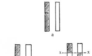
Vacuum-press-chamber molding
This method is based on transmitting air compression pressure through an elastic diaphragm to a workpiece laid on a rigid matrix-mold. The inner surface of the product is decorated with a matrix, and the outer surface with a rubber bag and tsulaga (Fig. 2.15). Laying the PCM package onto the mold is done manually using the techniques described above.
The elastic bag is secured to the base of the mold, thereby forming a hermetically sealed volume. The tsulaga is rigidly fastened to the mold with cap clamps. Pressing
carried out by supplying compressed air to the bag. Under pressure, the bag is stretched in the chamber and pressed tightly on one side to the workpiece laid on the mold, and on the other side to the surface of the tsulagi. After which the matrix is heated, and the product is cured. The heat treatment and pressing modes are determined by the properties of the PCM components, the design and dimensions of the product. Typically, the pressing pressure in the chamber does not exceed 0.5 MPa. To avoid changes in shape, the finished product is cooled under pressure and then removed from the mold.
Due to the difference in pressure inside the elastic bag and the surrounding air, the form experiences significant stress. Therefore, air molding molds are made stronger and more rigid than vacuum molding.
Almost any fibrous and layered materials can be formed using this method.
2.5. Features of the design of parts taking into account
contact molding and forming technologies
with elastic diaphragm
It may seem that changing the configuration or thickness of a new product is quite simple. However, when molding parts in an open mold, these changes must be made taking into account all possible consequences.
1. Before molding the part, the material must be placed in the mold strictly in accordance with its outline. If there are sharp corners (90° angle without rounding), the mats do not cover the entire surface of the mold, and air bubbles form behind the outer resin layer near the corners. In the presence of
2.5. Part design features
internal right angles made without roundings, the material will not adhere to the surface of the mold. If the shape has external right angles, the CM will also not be able to tightly cover them.
To prevent these phenomena, it is recommended to round the internal and external corners to a radius of 3.00... 10.00 mm. In this case, the CM will more fully follow the outline of the form, i.e. drape will be better. Places of sharp surface transitions are areas of high stress concentration, where delamination and cracking of the material can occur. It is obvious that such places should be avoided in structures and self-reinforcing transition sections of moderate bending should be provided.
2. To change the thickness of a product molded in an open mold, the number of layers of material should be increased (or decreased). If sudden changes are necessary, the layers must be carefully laid exactly in accordance with the outline of the form, which, however, increases the cost of manual labor. In places of thickening, stress concentration occurs and, as a result, delamination of the material occurs. Therefore, the appearance of such high-stress zones must be avoided. For this purpose, it is recommended to change the thickness of the product gradually, laying layers of material in steps or like roofing tiles.
3. A round hole should be considered the most convenient for molding; the most inconvenient is a hole with sharp, unrounded corners. To prevent stress growth, it is recommended to increase the radii of curves in the corners, and gradually increase the thickness of the product in sharp corners or provide flanges around the holes.
4. Products made from PCM are often obtained by joining several individual parts. Therefore, depending on the strength (from greater to less), connections should be distinguished: overlap-exact, shear-type; butt; oblique overlaps, working on tearing (delamination).
Lap joints are the lightest and most widely used in the manufacture of PCM parts (Fig. 2.16, A). Their shape and loading characteristics (shear) require the use of adhesives, which ensures maximum joint strength. Destruction of the lap joint
2. TECHNOLOGY OF STRUCTURES FROM POLYMER COMPOSITIONS
failure under the influence of shear stresses occurs when, with increasing load, it begins to tear.
As the load increases, the connection point rotates, while the acting forces are located on the same axis (see Fig. 2.16, A). This rotation causes the material to bend and delaminate at the ends of the overlap. If the loads continue to increase, the delamination stresses may exceed the adhesive strength and the joint will quickly fail. However, if the edges of the overlap are beveled, the structural rigidity is reduced, resulting in increased joint strength without increasing its surface area. Moreover, with proper preparation of materials, it is possible to obtain even higher strength values for the same shear surface by connecting the parts obliquely ("in the miter") (see Fig. 2.16, b).

Rice. 2.16. Examples of technological connections when gluing
materials:
A - lashed; b - upside down (in "mustache"); V - butt: 1 - a layer of glue;
2, 3 - hard materials; 4 - intermediate layer
A butt joint with a layer of glue and intermediate layers is used when gluing hard materials; it only works in tension (Fig. 2.16, V). Its strength usually ranges from low to medium values, and it is easily
A tear joint is a structure in which stresses are concentrated along the line along which one bonded material is bent from another, resulting in unbalanced tensile stresses in the materials (see Fig. 2.16, V). In such a connection, only that section of the adhesive seam that is located at the delamination point is under load, and the remaining sections of the seam remain unloaded until the delamination zone reaches them.
5. The minimum technological slope angle should be 2° (zero slope - only in split molds). Undercuts are not desirable and are allowed only in split and rubber forms.
6. The minimum actual thickness of products when molding by manual laying of layers should be set to 0.8 mm, when spraying - 1.5 mm. The maximum actual thickness, in principle, is not limited, but taking into account curing it should be 8... 10 mm. Standard thickness variations: when molded by manual laying of layers - from +0.8 to -0.4 mm and when sprayed - from +0.64 to -0.64 mm. The maximum increase in thickness is not limited.
2.6. Shaping yes
1. TECHNOLOGY OF STRUCTURES FROM POLYMER COMPOSITIONS
Pressure impregnation
The essence of this molding method is that the binder is supplied under pressure to the lower hole of the mold and gradually it fills the space between the matrix and the punch, displacing air from the material laid on the matrix (Fig. 2.17).

Rice. 2.17. Scheme of impregnation of a package of material under pressure:
/ - punch; 2 - package of material; 3 - matrix; 4 ~ tank with binder;
5 - installation for heating organic coolant; 6 - compressor
The ability of the resin to spread in a closed mold under pressure is used to manufacture products with a simple symmetrical shape. This forming method makes it possible to obtain structures with high accuracy of geometric dimensions, constant density over the volume of the wall material, while the wall will have virtually no voids or local delaminations. Such requirements must be met, for example, when manufacturing various types of aircraft fairings. It is in this area that the method is most widely used.
The method of manufacturing molds for impregnation differs from the method of manufacturing molds for contact molding; it is more labor-intensive, since it is necessary to ensure with high accuracy a gap between the matrix and the punch equal to the wall thickness of the product. Therefore, for the manufacture of metal and non-metallic molds, a model made of the same material and with the same wall thickness as the product is used. This model is usually molded on a plaster mandrel and is an accurate three-dimensional mock-up of the surface of the product. At the same time, the model serves as technological equipment for manufacturing the lower part of the mold (matrix) and the upper part (punch).
2.6. Pressure shaping
2. TECHNOLOGY OF STRUCTURES FROM POLYMER COMPOSITIONS
The wall thicknesses of the matrix and punch for a particular product are determined experimentally.
Preparation of the die and punch surfaces involves applying release agents or release films in the same way as in the case of contact molding. Dry reinforcing material is laid out on the matrix before it is covered with the upper part of the mold and screwed together.
The material placed between the positive and negative molds must be dried before impregnation. For drying, a stream of hot air supplied from a heater is passed through the mold. In some cases, for small-sized products, the reinforcing material is “washed” with the same resin that is included in the binder. In this way, air bubbles are removed from the material and thereby eliminate the risk of formation of unfilled resin areas in the product. However, for large-sized products, the “washing” operation is not economically profitable.
The pressure of the binder during the impregnation process, acting on the walls of the matrix and the punch, expands the gap between them and promotes uniform filling of the reinforcing material with the binder. Therefore, in this case, slight unevenness when laying the material on the matrix is not significant. The rate at which the binder rises in shape is limited by the conditions of high-quality impregnation. If this speed is exceeded, the binder will fill the air bubbles before they separate from the fiber. Then the bubbles can only be removed by “rinsing” with a new portion of clean resin; Such washing takes so long that it completely depreciates all other advantages of the process.
For high-quality impregnation, the temperature, viscosity and speed at which the binder rises must be regulated and controlled.
After the binder appears in the outlet holes in the upper part of the mold, the supply of binder is stopped, and in order to speed up the curing process, the mold begins to be heated. In some cases, the impregnation of the material is carried out in an already heated form, for which appropriate heating devices are used. Sometimes copper wire wrapped around a heater is used as a heater.
forms. In some cases, curing of products is carried out in ovens in which the mold is placed. Curing parameters are determined by the type of binder used.
In the case where it is necessary to ensure high productivity of the process, short chopped fibers (50...70 mm), pre-formed to the shape of the product, are used. However, in this case it is impossible to obtain a high-strength material.
Vacuum impregnation
The process of molding products by impregnation in a vacuum (technology of preparing the mold, laying the workpiece material) is similar to the process of molding by impregnation under pressure. The diagram of vacuum impregnation is shown in Fig. 2.18.

Rice. 2.18. Molding pattern:
/ - binder; 2 - locking device; 3 - punch; 4 - sight glass; 5 - vacuum system; 6 - tank for excess binder; 7 - workpiece; 8 - matrix; 9 - channel for passing the binder; 10 - elastic gasket
When using a vacuum, the mold elements must be sufficiently rigid to prevent squeezing of the reinforcing material and preventing the free flow of the resin due to possible flattening of the die or punch. If
The material *is unevenly shaped, then the resin will not pass through some compacted areas, and these areas will remain unimpregnated. As the resin approaches the upper outlet, it is necessary to increase the vacuum to ensure further movement.
2.7. Shaping by pressing in molds
In general, the method of molding products by pressing is a process in which the material in the mold takes on a given configuration, determined by the matrix and the punch, and its curing occurs in the mold.
Currently, about 50% of all reinforced plastic products are produced using this method. It is used when high productivity, accuracy and reproducibility of parts are required. At the same time, high quality products are achieved at minimal cost. But even when production volumes are small, such as aerospace parts and other high-performance products, requirements for precision and repeatability of parts require the use of molding methods.
For all molding cases, molds are used. A mold or set of molding parts usually consists of two main parts: a matrix and a punch, and one of them fits into the other when the mold is closed, maintaining a given gap between them equal to the thickness of the molded part.
Depending on the reinforcing material used, the design of the mold, and the method of loading the material into the mold, there are three main methods of shaping PCM products: direct pressing; injection molding; thermocompression pressing. Features of the technology for manufacturing parts using these methods are described below.
2. TECHNOLOGY OF STRUCTURES FROM POLYMER COMPOSITIONS
Direct pressing
This pressing method is one of the most common in the production of pressed products. The method of direct pressing of reinforced compositions does not differ significantly from the molding of plastics. The main difference lies in the nature of the material itself from which the part is pressed. Instead of free-flowing resins or powders, sticky fibrous mass, tableted PCM, impregnated mats, fabrics or preformed PCM blanks or premixes are supplied for molding.
|
|

Premix is a fiber-reinforced thermoset composition which, once formed, requires no further curing and can be molded by applying just enough pressure to flow and compact the material.
In most cases, hydraulic presses are used for pressing PCM products, since they provide constant pressure on the pressed part during the entire pressing time and, in addition, they are simpler and more reliable to operate than mechanical presses. Hydraulic presses are driven by fluid pressure (water or oil) supplied by a pump to the press cylinder.
Hydraulic presses are usually used with one working cylinder (bottom-mounted or top-mounted) or with two working cylinders (vertical and angular).
In Fig. Figure 2.19 shows a diagram of a hydraulic press with a lower position of the working cylinder.
The top plate and the press frame are interconnected by a column
2.7. Shaping by pressing in molds
us, perceive the press force developed by the plunger of the working cylinder. When the plunger is raised, a mold installed on the lower movable plate with the material loaded into it is pressed against the upper fixed plate, and the material in the mold is pressed. When the water supply to the working cylinder is stopped and it communicates with the drain line, the press plunger and the movable plate, by the force of their weight, displace the liquid from the working cylinder and lower.
Presses with lower pressure are most often used for pressing products in removable molds. Such presses sometimes have intermediate movable plates, which are called floor presses.
To heat removable molds, heating plates, insulated from the supporting surface with heat-insulating gaskets, are fixed on the lower movable plate and the upper fixed plate of the press. The intermediate movable plates of floor presses are also heated.
Presses with an overhead working cylinder, i.e. presses with upper pressure (Fig. 2.20) are used mainly for direct pressing of PCM parts in stationary molds. The difference between these presses and presses with lower operating pressure is that they have auxiliary return cylinders (return cylinders) and an ejector cylinder mounted on the lower fixed plate. Return cylinders serve to lift the movable working parts of the press - the upper movable plate and the plunger. The ejector cylinder ensures the removal of pressed parts from the mold. Presses with an overhead working cylinder, as a rule, are only single-deck.
The main element of the technological equipment of the pressing process is the mold, the complexity and cost of which determine the quality and cost of the products.
In accordance with the pressing method, molds are divided into molds for conventional pressing (compression) and injection molds for injection molding; according to the nature of the operation - into removable, semi-removable and stationary, depending on the number of design nests (number
simultaneously pressed parts) - into single-cavity and multi-cavity.
According to the principle of the design cavity, direct compression molds are divided into open, semi-closed and closed molds.
|
|

Rice. 2.20. Diagram of a hydraulic press with an overhead working cylinder: 1 - bed (lower movable plate or work table); 2 - column; 3 - upper fixed plate (head); 4 - working cylinder; 5-plunger; 6 - upper movable plate; 7- stops; 8 - grooves in the upper movable and lower fixed plates for securing the mold; 9 - ejector; 10 - reverse cylinders (return cylinders); // - support frames; 12- ejector cylinder
Open type molds(Fig. 2.21). Such molds do not have a loading chamber; compaction of the material pressed into them is achieved due to friction, which occurs when the material flows out of the forming cavity through the gap between the punch and the matrix. Therefore, for pressing in an open mold, a significant excess of material is required (up to 10...15%).
2.7. Shaping by pressing in molds
2. TECHNOLOGY OF STRUCTURES FROM POLYMER COMPOSITIONS
changes as the gap between the punch and the matrix decreases and depends on the properties of the material, then the use of open molds for pressing products from thermosetting plastics is possible only in the case of pressing simple products with a small height of vertical walls. Parts pressed in open molds have low height accuracy.
Semi-closed or overflow molds(Fig. 2.22). In them, as in open-type molds, the necessary compaction is achieved due to friction that occurs when the material flows out of the molding cavity. However, the gap through which the material flows is regulated and remains almost constant throughout the entire molding process. Such molds provide a greater degree of compaction of the pressed material than open-type molds, which makes it possible to form complex parts in them. In semi-closed molds, the dies have
overpress space - a loading chamber that is a continuation of the forming nest.
The loading chamber is used to place a sample of press material into it. For pressing in semi-closed molds, less excess material is required than for pressing in open molds.
Semi-closed molds are used mainly for pressing plastic products.
|
|

| Rice. 2.23. Scheme of a closed type mold; 1 - punch; 2 - matrix |
Closed (piston) molds(Fig. 2.23). It is characteristic that during pressing the material practically does not flow out of the forming nest. The outline of the punch of such molds in plan exactly matches the outline of the product. This complicates the production of molds and causes their relatively low operational durability. However, in such molds, greater compaction of the material is achieved with constant pressure on it from the punch during the entire pressing time. When pressing in closed molds, it is necessary to accurately select the portion of the material to be pressed. For industrial production, metal molds are mainly used, made of wear-resistant hardened steel of type 4X13, U8A, KhVG, 12KhNZA, U10A and others.
The surface quality of molds for the manufacture of reinforced compositions does not necessarily have to be high. The presence of fillers imposes certain restrictions on the roughness and gloss of the pressed product, regardless of the quality of the polished surface of the mold. Nevertheless, to protect the mold from corrosion, better separate the finished products, and remove traces of tools from machining, it is advisable to chrome plate its surface (coating thickness 10...25 microns).
To carry out experimental pressings or to press several products, it is possible to use wooden, plastic or plaster molds. At low pressing pressures, molds can be made from non-ferrous alloys
2.7. Shaping by pressing in molds
casting method, but they have a short service life, although they are cheaper than steel.
The demolding stage is the most critical stage in the molding process. To facilitate this operation, firstly, it is necessary to take into account the technology of its manufacture at the design development stage, and secondly, use anti-adhesive lubricants or release materials that prevent the product from sticking to the surface of the mold.
Materials used as anti-adhesives can be divided into two types:
film materials or solutions forming a protective film;
liquid or solid substances that soften at pressing temperature and do not form a continuous film.
The first group includes solutions of polyvinyl alcohol in water, solutions of sodium alginate, cellophane, lavsan, fluoroplastic and other materials. In all cases, the film influences the formation of surface defects of the molded product.
The second group consists of lubricating films that are more convenient for application to equipment: wax, paraffin, silicone-organic lubricants (type K-21), oil residues, etc.
When choosing release agents, it is necessary to take into account the molding temperature and their effect on the binder of the molded product.
The main parameters of pressing processes are temperature, pressure, time.
During the molding process, the semi-finished product must be heated to a certain temperature in order to give it the required plasticity, i.e. ability to shape. For thermoset PCM, heat is also necessary for curing. However, the possibility of increasing the molding temperature is always limited by the temperature of destruction and decomposition of the binders. Heating and cooling of large-sized products is carried out by heaters located in molds. In other cases, heating devices can be located both in the molds themselves and externally - in the upper and lower plates of the press. Curing time of products
2. TECHNOLOGY OF STRUCTURES FROM POLYMER COMPOSITIONS
there should always be more time required to fill a given mold with material.
During the molding process, pressure is necessary to compact the heated plastic material and give it the shape of the product. Pressure must be applied to the material until the molded product loses its plasticity and becomes hard as a result of heating (for thermoset compositions) or as a result of cooling (for thermoplastic compositions).
The process time is determined by the rate of heating of the material to a plastic state and, mainly, by the rate of solidification or cooling rate.
|
|

These three main parameters of the molding process - temperature, pressure, time - are interconnected. Changing one parameter entails changing others. For example, increasing the molding temperature of thermoplastics improves their ductility and therefore reduces the required pressure and molding time.
The main process parameters are determined in each specific case depending on the PCM components, the composite reinforcement scheme, the geometry and shape of the product and are worked out experimentally.
Direct pressing (Fig. 2.24) consists in the fact that one or another pressing material is placed in a matrix heated to the molding temperature, which is subject to pressure R the upper half of the mold - the punch, heated to the same temperature. Under the influence of temperature, the material acquires the necessary plasticity and, under pressure, is distributed over the design
2.7. Shaping by pressing in molds
cavity, filling it. Complete closure of the mold (closure) occurs at the moment of final design of the part. The mold is closed at low speed so that air inclusions are forced out of the cavity. The molded product is held in the mold under pressure for some time necessary to cool the thermoplastic composite or heat the thermoset material, after which the mold is opened and the product is removed using a forceful ejector r in.
If pressing modes are incorrectly selected or materials are of poor quality, the following defects may appear in products: air bubbles around protruding areas on the surface of the part; places containing an insufficient amount of binder due to an excess of reinforcing filler; cracking of the binder and places containing its excess; matte surface and stains on the product.
Each defect has its own causes; recommendations for their elimination are usually reflected in a document such as a technological regulation.
Let's look at the features of direct pressing.
A. When designing the part, you can press it into it once
various fittings (screws, nuts, rods, etc.), which
will be firmly held in the part.
b. Heating of the material occurs gradually from the heat
nok of the heated mold deep into, and therefore in pro
During the molding process of a product, different layers of material can
have different temperatures.
V. The temperature difference across the thickness of the product leads to
the formation of internal stresses and defects as a result
uneven curing process or vulcanization
nization.
d. There is a danger of damage to thin and low-strength
ny design elements of the mold or press
reinforcement inserted into the part, since the material is under pressure
begins to fill the forming cavity even before
the moment when it warms up completely and acquires
sufficient plasticity. To eliminate this danger in
In most cases, the pressure mode is programmed and
Several preliminary pressings are used.
2. TECHNOLOGY OF STRUCTURES FROM POLYMER COMPOSITIONS
In addition, with the help of pre-pressing, volatile and vapors of moisture are removed in a short period of time at the initial stage of the material’s curing.
d. On molded products, burrs (burrs) always form in the mold parting plane.
The direct pressing method can be used to produce products from any materials, both thermoplastic and thermosetting. In practice, this method is used mainly for the manufacture of parts from thermosetting CM. Using it for molding parts from thermoplastics is impractical, since in this case it is necessary to alternately heat and cool the mold during each molding cycle, and this significantly increases the duration of the process.
Approximate modes of direct pressing of parts, which are used as a guide when developing the molding process, are given in Table. 2.5.
Table 2.5 Approximate modes of direct pressing
Various methods of impregnation of the reinforcing material and pressing modes make it possible to obtain a filler content in the composite from 20 to 50%.
injection molding
Injection molding consists in the fact that the material to be pressed is loaded into the loading chamber of a pre-closed mold (Fig. 2.25). Heating from the walls of the loading chamber and acquiring the necessary plasticity, the material, under pressure from the injection molding punch, enters through the sprue channel into the mold cavity.
2.7. Shaping by pressing in molds
and fills it out. After waiting necessary for hardening, the mold is opened and the finished product is removed along with the sprue residue.

Rice. 2.25. Diagram of a mold for injection molding on presses with one working cylinder:
1 - conical matrix cage; 2 - wedge matrix; 3 - loading chamber; 4- injection molding punch; 5 - molded product; 6- ejector; 7 - sprue channel
Features of injection molding are as follows:
a) it is possible to produce parts with low strength or through
fittings and parts with deep holes of small diameter,
since the material enters the forming cavity of the press
the forms are already in a plastic state and are not able to exert
on the design elements of the mold and pressed
reinforcement with significant deformation forces;
b) the process of forming the material proceeds faster than
with normal pressing;
c) in parts obtained by injection molding, there is no
large internal stresses occur due to smaller
temperature difference across the wall thickness of the part;
d) on parts made by injection molding, prak
there is virtually no veil left, since the cavity that forms
the mold formed by the punch and the matrix is tightly
is closed even before it is filled with material. I will maintain accuracy
The variation in the dimensions of parts with this method is high, and the mechanical
2. TECHNOLOGY OF STRUCTURES FROM POLYMER COMPOSITIONS
Technical modification of parts is reduced only to cutting off the sprues and cleaning up places immediately;
d) injection molding uses more material
la than with direct pressing, since the material fills
gating channels and pressed into the loading chamber
its remainder;
e) injection molds are more complex and up to
face of molds for direct pressing.
The injection molding method can be used to produce products from rubber compounds and powdered plastics. Plastics with fiber fillers lose up to 50 % its strength. Laminated plastics cannot be processed by injection molding, since the material is not able to pass from the loading chamber of the mold into its forming cavity through the narrow gating channels.
Injection molds differ from direct compression molds in that they have a loading chamber for the material being pressed, separated from the forming cavity and connected to it by gating channels. The forming cavity of the injection mold is closed before pressing, and the material enters it in a plastic state from the loading chamber through the gates.
There are two fundamentally different design options for injection molds - injection molds for pressing on special presses with two working cylinders (Fig. 2.26) and injection molds for pressing on conventional presses with one working cylinder (see Fig. 2.25) .
To press a part in a mold, the material is poured into the loading chamber, then the upper half of the mold is lowered onto the lower half and held under the pressure of the plunger of the upper working cylinder of the press so that the mold does not open when filled with material. Under the pressure of the lower working plunger of the press, the injection molding punch rises and squeezes the material out of the loading chamber along the gates into the forming cavity. After pressing is completed, the mold is opened and the products are pushed out with an additional stroke of the injection punch.
The method makes it possible to develop pressing pressures of up to 35... 150 MPa for parts made of thermoplastics and thermosetting plastics.
| 2.7. Shaping by pressing in molds |
| Thermocompression pressing As the size or complexity of the configuration and design of products made from thermoplastic composite materials increases, the difficulties in ensuring the required quality increase sharply, since the capabilities of traditional molding methods and the corresponding technological equipment are limited. Rigid molds with an increase in the overall dimensions of the product become unprofitable, their cost and labor intensity of production increase, in addition, there are often no presses with tables of the required sizes. The process of molding using elastic membranes at temperatures above 180 °C is complicated due to their insufficient reliability, a limited number of molding cycles (usually 1-3 cycles) and, as a result, an increase in scrap. By |
Closing force

Rice. 2.26. Diagram of a mold for injection molding on presses with two working cylinders:
/ - injection molding punch; 2 - loading chamber; 3 - plane of the connector; 4 - product; 5 - gating channels; 6, 7 - upper and lower parts of the matrix
com accordingly and obtain more complex and precise parts in configuration. This is also facilitated by a higher heating temperature compared to direct pressing, which reduces the viscosity of the material and speeds up the molding time.
The mode of flow of softened material through the gating channel of the matrix not only brings this process closer to casting, but also contributes to more uniform heating of the material and thereby reducing the level of residual internal stresses in the walls of the part. The disadvantages of the method include the small size of the molded parts, the complexity of manufacturing dies and a lower material utilization rate than with direct pressing.
2. TECHNOLOGY OF STRUCTURES FROM POLYMER COMPOSITIONS
For these reasons, the thermocompression method of molding products from TCM is of great interest.
The technological equipment for implementing this method (Fig. 2.27) consists of a restrictive part made, for example, of metals and an elastic forming element (EFE),
characterized by CTE in the range (250...500) 10~ 6 °C -1. The assembled package is formed in the restrictive part of the equipment due to the thermal expansion of the EFE when heated. Due to the significant difference between the CTE of the materials of the restrictive part of the equipment (10...25) 10 °C -1 and the EFE, molding pressure arises, under the influence of which the TCM package is compacted. If the EFE is inserted into the restrictive part of the equipment with a certain initial gap 5, then heating the equipment to a certain temperature is accompanied by an increase in pressure R, which can be calculated using the formula
P = k p ∆T.
Here k- thermal compression coefficient of the EFE material, characterizing the increase in pressure inside the closed volume in which the EFE is located when it is heated by 1 °C, MPa/°C:
k p =αE/(1-2μ)
where a, E, q - CLTE, elastic modulus and Poisson's ratio of the EFE material; ∆ T- difference between current temperature T and temperature T δ, at which the gap between
EFE and the restrictive part of the equipment.
If we consider the restrictive part of the equipment to be absolutely rigid, then for rubber To - 0.5...0.7 MPa/°C. Therefore, when heated to a temperature of 300 °C and above, it is possible to create almost any molding pressure necessary for the manufacture of products from TCM.
The thermocompression method can be carried out using two main types of technological equipment: with constant (Fig. 2.27, A) and variables (Fig. 2.27, b) molding volumes.
| 2.7. Shaping by pressing in molds |

Rice. 2.27. Tooling for thermocompression molding with constant (A) and variables (b) volume:
/ - metal punch; 2 - metal matrix; 3 - elastic forming element; 4 - sealable package; 5 - support strips; 6 - fixing elements; 7 - pressure sensor; 8 - guide columns-clamps; 9 - elastic calibrated elements
In the first case, the volume of the forming cavity remains constant throughout the entire molding cycle. By adjusting the gap between the EFE and the TCM package, it is possible to vary the temperature of the beginning of the impact and the final level of molding pressure within a wide range.
In equipment with variable volume, one of the elements of the restrictive part is made movable, but is supported by elastic calibrated elements. When the pressure set by the elastic calibrated elements increases, some movement of the punch occurs along the columns, while the molding pressure is maintained at a given level.
In equipment with EFE, it is possible to simultaneously mold and assemble products of an integral design, for example, panels of various configurations with an internal power set. Due to the elasticity of the EFE material and high CTE values, the extraction of EFE from various undercuts is carried out without much difficulty. At the same time, high-quality compaction of all surfaces is ensured, including surfaces with a small transition radius.
2. TECHNOLOGY OF STRUCTURES FROM POLYMER COMPOSITIONS
An increase in the processing temperature of structural TCM narrows the range of choice of EFE materials. The peculiarity of operation is that EFEs are under conditions of all-round compression in a closed volume at elevated temperatures. Thus, EFE materials for processing TCM must have the following properties:
high elasticity necessary to transmit pressure evenly in all directions;
stability of properties during long-term exposure in a closed volume at operating temperatures;
values KLTR not lower than 250 Yu -6 °C -1, constant during operation.
It has been established that of the elastomers mass-produced by the domestic industry, only rubber based on silicone rubbers have properties that meet the requirements. Compositions based on them provide different CTE values, have good thermal conductivity, and high dimensional stability during repeated use. At temperatures up to 200 °C, the EFE material can be rubber based on SKTV-1 silicone rubber.
When using the thermocompression pressing method, it is possible to obtain equal-thickness products with high-quality molded walls. At the same time, the labor intensity of manufacturing tooling is reduced, and the level of physical and mechanical characteristics is increased due to a more uniform distribution of molding pressure.
Fibrous impregnated material is laid out on the form to be processed (if necessary, it can also be impregnated on the form). A vacuum bag with metal pipes connected to rubber hoses is placed on it. Vacuum pumps pump air out of the sealed cavity formed between the fiberglass diaphragm so that the pressure there is lower than that applied to the diaphragm.
Due to the resulting pressure difference on different sides of the diaphragm, it is pressed against the molded product, compacting the material and giving the required shape.
Hardening occurs when individual layers of fiberglass are bonded together. Compaction of the composition eliminates voids and removes excess resin.
When curing diaphragm molded products, it is necessary to avoid bubble formation and carefully control pressure, temperature, and the fiber-to-resin mass ratio.
Molding pattern:
a) position before vacuum b) position after vacuum
1 – form
2 – vacuum bag
3 – impregnated glass filler
4 – metal pipe
5 – stuffing box
6 – clamps
7 – molded product
5.4. Autoclave molding. Components. Operations. Equipment.
Modes .

1 – channel for connection with atmosphere or vacuum
2 – mold plate
3 – manifold for sucking air from the bag
4 – diaphragm seal
5 – side outlet
6 – elastic partition
7, 8 – layer with ventilation hole
9 – diaphragm
10 – intermediate plate
11 – perforated layer
12 – absorbent layers
13 – separating fabric
14 – outer layer
15 – laminated reinforced plastic
During autoclave molding, a pressure of 0.35 - 0.7 MPa is maintained to compress the layer package during curing, while heating with hot gases is carried out. At the same time, the material is evacuated to remove trapped air and volatile products.
Vacuum is usually applied during the initial stages of curing cycles, while pressure in the autoclave is maintained throughout the heating and cooling cycle. Atmospheric or vacuum vents are designed to remove volatile products and trapped air from the curing FRP stack. Compared to other molding methods, the elastic diaphragm autoclave method produces products with more precise thickness and less porosity.
Lecture 15.
5.5. Winding. Components. Operations. Equipment. Modes.
Winding is a method of processing CM into products in which the filler is previously
coated with a binder (dry winding) or impregnated during winding (wet winding) is continuously fed at a certain angle onto a rotating removable mandrel, which, after winding, is placed in a heat chamber to cure the product; after curing using a capstan, it is pulled off the mandrel.
This method of processing CM into products includes a biaxial method, in which each subsequent spiral layer is applied row by row, intersecting fibers is excluded.
Oblique cross, in which when the spreader passes the traverse of one cycle, the thread is laid in the form of a continuous spiral with a change in direction, at opposite ends.
Circular, in which winding occurs perpendicular to the axis of rotation.
Uniaxial a method in which the thread path makes a full stroke along the length of the spreader, after which the next one lies next to the previous one.
Planetary, in which the thread path lies in a plane intersecting the winding surface.
The fibrous filler, pre-impregnated with the binder, is pulled at a speed of 0.6 - 6.1 m/min through the forming hole, heated by a die of a certain shape, where the fiber filler bundle is compacted.
It is used for the production of various cylindrical products made of fiberglass (pipes, tanks, etc.). Currently, winding of impregnated glass fabrics and canvases or glass strands and tapes onto a mandrel is used. The simplest method for manufacturing fiberglass pipes is considered to be the periodic winding method. Pipes are made on a specially winding or lathe machine adapted for these purposes. At the beginning of the process, strands, threads, meshes, fabrics or canvases are unwound from rolls, impregnated with synthetic binders, and then fed under uniform tension onto a rotating metal mandrel, which determines the internal diameter of the product and its configuration. Before winding, the mandrel is first degreased, lubricated with a thin layer of adhesive lubricant, and wrapped in cellophane. The figure shows a diagram of the manufacture of a long cylindrical product from threads or strands with simultaneous impregnation during winding.

1 - movable table
2 spools of threads or strands
4 - impregnation bath
5 - liquid binder containing no solvent
6 - squeezing rollers
7 - screw for moving the table
8 - mandrel
9 - drive to the mandrel
10 - product
11 - creel.
In accordance with. With this scheme, spools of threads and strands are inserted into a creel located on a movable table; this table, with the help of a screw 7 or a rod, is able to move back and forth along the product being wound during winding. From the creel, the threads are collected into a bundle, this bundle passes through an impregnation bath 4 filled with a liquid binder without a solvent, then between squeezing rollers 6, which serve to remove excess binder. The impregnated beam, during the movement of the table, is wound at a certain angle onto a mandrel 8 having a drive 9 for rotation. After one layer of impregnated filler has been wound over the entire length of the product, the table movement is reversed. And the next layer is wound at an opposite angle, resulting in a cross-layer arrangement of threads
After obtaining a product with the desired wall thickness, it is removed from the machine and placed in an oven to cure the binder that has penetrated the pores of the filler during impregnation and winding. Since the binder penetrated into the pores of the filler due to capillary forces, when choosing threads and their degree of twist, one should take into account the possible adverse effects of shrinkage phenomena that occur during hardening of the binder.